
Recap
In Part 1 we learned that:
The induction machine’s main components are the stator, the rotor, the winding and the airgap between the rotor and stator. The airgap is not an actual component, but its role is paramount.
A three-phased voltage creates a rotating field; a space vector with constant amplitude. The windings are also installed with a 120° phase displacement in the stator’s circumference, so that rotating field is actually rotating around the stator circumference.
The rotating field’s speed is determined by the supply frequency and the number of poles. A pole pair is a set of three phased windings. Duplicate them, and we get two pole pairs and half the mechanical speed.
Magnetomotive Force (MMF) is what drives the magnetic flux through the iron as a magnetic circuit. MMF is given directly by ampere-turns; current and number of winding turns. The iron has reluctance which opposes the flux. The air gap is important because it has very high reluctance.
The magnetic field strength (H) and magnetic flux density (B) are two different things. The winding current creates the H-field, and the magnetization of iron add enormous amounts of B.
Iron saturates when the magnetic domains reach their limit. Adding more current in this state, yields very little B in return. When the machine is voltage-controlled, this creates a spikey current waveform.
Magnetic flux belongs in the iron (magnetic circuit), while flux linkage is how that flux affects a winding (in the electric circuit).
Changing flux linkage induce voltage in a winding. Faraday’s law is behind the induced back-EMF and Lenz’ law give the opposing polarity.
In a voltage controlled machine, the applied voltage and frequency determine the magnetic flux, and the magnetizing current simply adjust according to the circuit as long as the voltage can support it.
The rotating field in the stator also induces voltage and current in the short-circuited bars in the rotor. This can only happen as long as there is a relative speed difference between the stator rotating field and the rotor rotational speed. This speed difference is what we call slip. Without it, an induction machine does not induce anything in the rotor.
When current is flowing in the rotor, the current sets up its own H-field and MMF. This field is interacting with the stator field, and makes the stator pull more current to maintain its field.
When the two fields interact, they create a sideways force in the airgap which add torque to the rotor.
And that was where we left off. Now we are going into the nitty gritty details about what is affecting the torque.
While part one spent considerable time on iron and magnetism, this part will spend similar amounts of time on vectors, animations and the rotor.
Forcing the rubber bands - Finally some torque, guys!
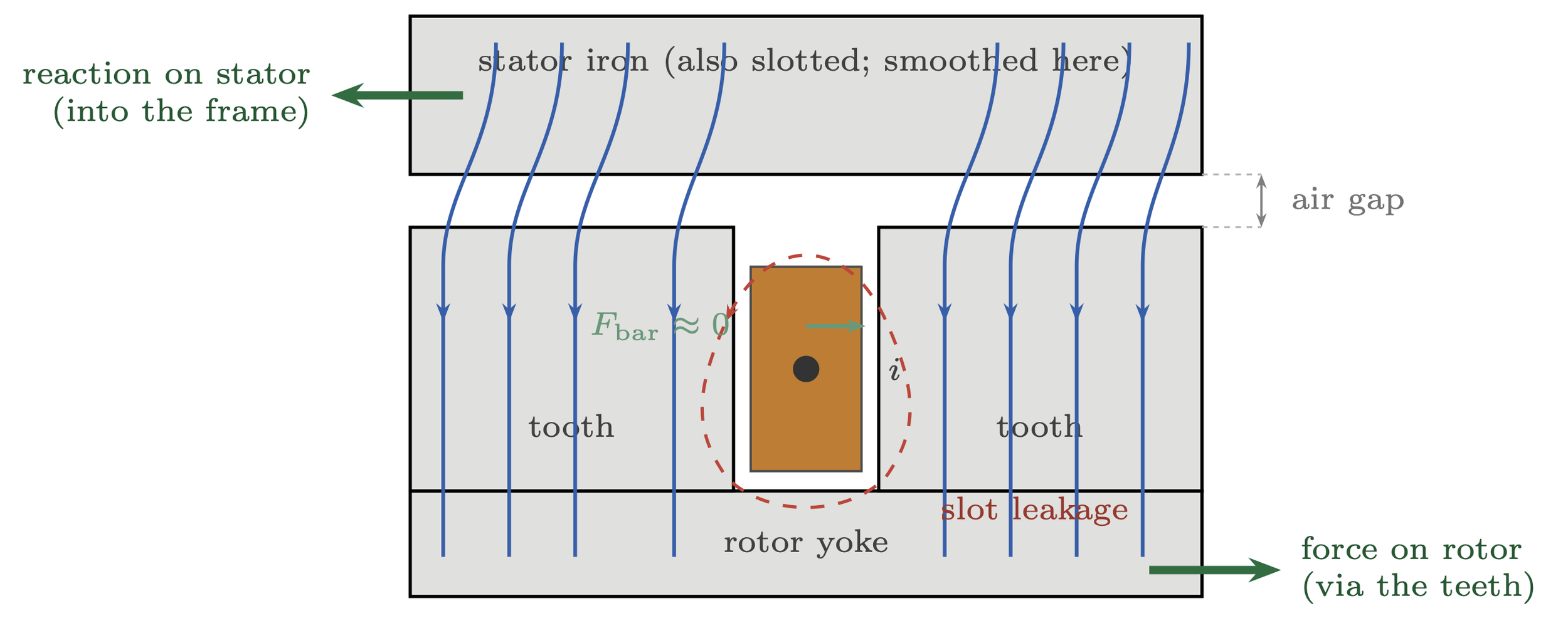
The skewed rubber bands: The last thing we discussed in part 1 was that when current flows in the rotor bars, their MMF creates a magnetic field which pushes the flux lines sideways. That makes the force act sideways and voilà: we got torque, and with torque the rotor finally spins.
This part of the never-ending explanation about what the heck field-weakening is, will deal with various vectors. We have just seen how the stator MMF vector and rotor MMF vector fight, and this is something we will dive deeper into.
But first, I want to quickly summarize four important vectors and how they “transcend” their domains. It is important to understand how the stator voltage vector sets the magnetic flux, and how the stator current sets the stator MMF. These two are pairs, and as pairs they go hand i hand:
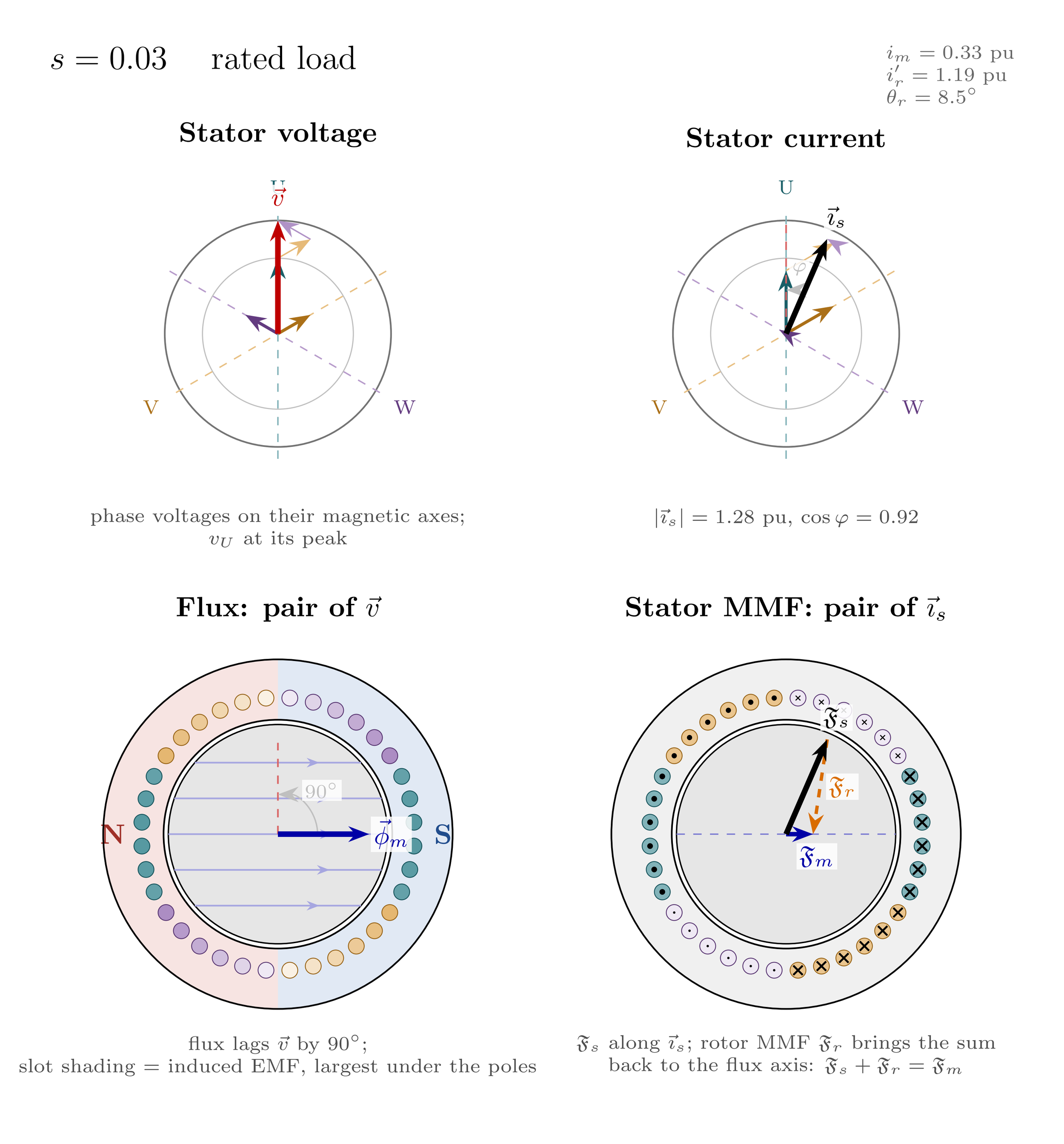
The stator voltage.
This is the supply voltage (v). If we subtract the voltage drops in the stator resistance and stator flux link leakage, we get the back-EMF (e). The voltage drops are proportional with stator current, i. At no load, v = e, and as load is increasing e gets smaller and sags slightly behind v as the inductive voltage drop has an angle.The magnetic flux.
This fella is locked to the stator voltage and always 90 degrees behind its space vector, thanks to Faraday.The stator current.
This is what you measure with a clamp meter, the total current entering the machine. It’s angle compared to the stator voltage is dependent on the machine’s power factor (which varies under load), but it is always lagging the voltage.The stator MMF.
This is given by the stator current. \(\mathfrak{F_s}\) always along \(i_s\). The direction of these two are always identical.
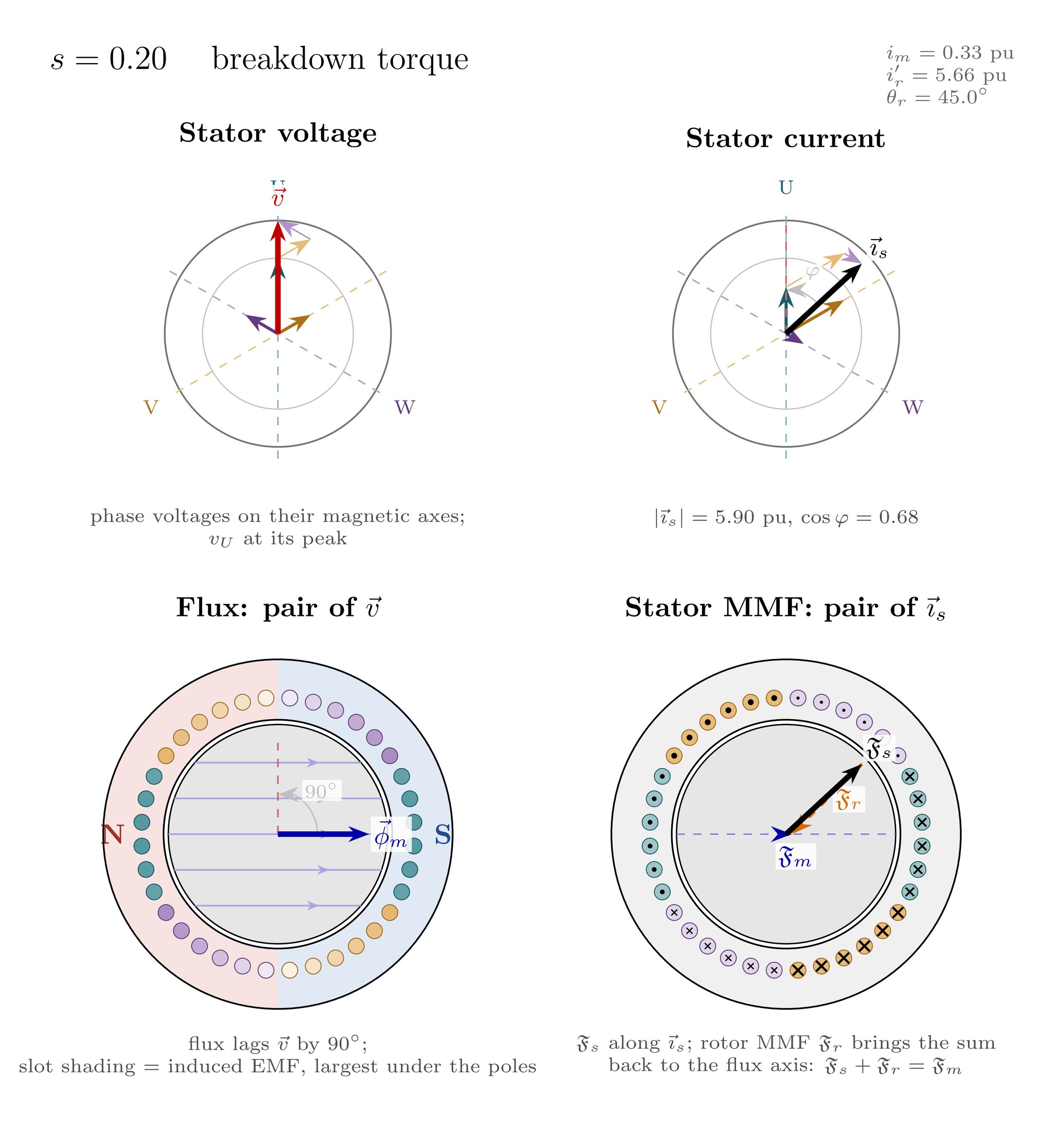
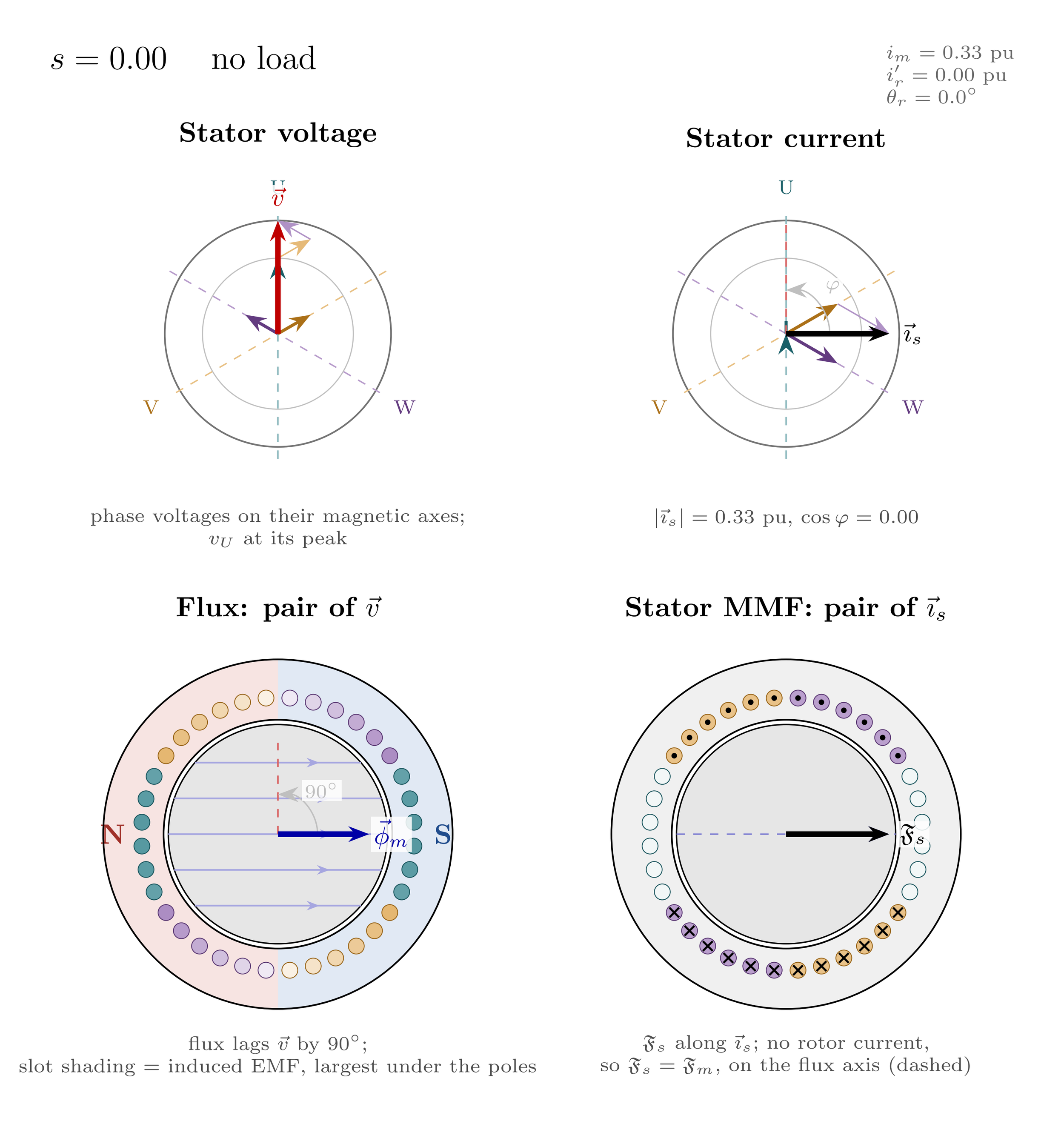
Below are these two pairs shown in three different settings: at no load (no rotor current), nominal load, and at breakdown torque (which will be thoroughly explained. don’t worry)
We see that:
At no load, MMF and flux are in phase. Just as in some of the figures in Part 1.
When load is increased, the stator MMF angle separates from the flux angle. This happens because when we add load, we also add current to the rotor bars. Which add their own rotor MMF. This rotor MMF and its effects is what we are going to dig into.
Now, that rotor MMF
The rotor MMF angle is given by two aspects.
First, the \(\Theta_r\) which we call the rotor angle.
This is the angle between the induced voltage (EMF) in the rotor bars, and the induced current. This is the same as \(\cos{ϕ}\) in normal power systems, a time-phase angle between to sinusoidal values; voltage and current. It is actually called rotor power factor in some litterature.
As we cannot exactly measure these values directly (because they are buried inside a rotating rotor...), we have a simpler method: divide reactance by resistance. Those two have the same relationship as the typical power factor:
\begin{equation} \Theta_r = s \omega \frac{ L_r}{R_r} \label{eq:def_theta_r} \end{equation}
Secondly: The s and ω are the slip and rotational speed (ω is also known as 2πf), together they form the actual frequency the rotor bar feels as voltage is induced by the passing stator field.
If we measure \(Theta_r\) relative to the flux, Φ, we obtain a space-phase angle: \(∠(Φ,(F)s)=90+Θ_r\).
So, the angle between the flux and the stator MMF is given by the rotor angle + 90 degrees. Those 90 are a fixed offset because EMF is always in quadrature (fancy name for “off by 90 degrees”) to the flux. Also ref point 2 above.
Now, the resultant MMF in the machine is the vector sum of the stator MMF plus the rotor MMF as shown below.
There is always only one MMF remaining in the motor; the resultant magnetizing MMF, F_m.
This is made by the stator MMF, F_s and the rotor MMF, F_r.
At no load, the magnetizing MMF, \(\mathfrak{F_m}\) is (almost) the same as the stator MMF, \(\mathfrak{F}_s\). However, when the rotor comes along with its own MMF, something happens:
The machine must keep its magnetizing MMF. It cannot change.
It is locked by the supply voltage, and voltage is our controlled variable which does not change unless we say it do.
To counter the effects of the rotor MMF, \(\mathfrak{F_r}\), the stator therefore pulls extra current.
In the two figures below you will see that \(\mathfrak{F_m}\) has the same magnitude and direction both when unloaded and loaded.
When unloaded, the \(\mathfrak{F_s}\) is equal to \(\mathfrak{F_m}\), ignoring the small friction losses. The stator MMF is entirely at the d-axis and therefore only supplying reactive power to the field.
When loaded however, the stator MMF become a different beast. Now, \(\mathfrak{F_r}\) is established due to the load, and with an angle of 90+\(\Theta_r\), and the stator has to establish a massive counter-MMF, \(\mathfrak{F_s}\), to maintain the magnetizing MMF, \(\mathfrak{F_m}\) at the same direction and magnitude.
Pay attention to how the rotor MMF is almost entirely at the q-axis, which is the torque producing direction. The increased stator MMF is therefore almost purely active power. We can actually read the machine’s actual power factor based on the stator MMF angle.
The small tilt in the rotor MMF caused by \(\Theta_r\) increases the consumed reactive power a little bit, as this is also compensated for by the stator MMF. The reason for this reactive consumption is the rotor’s leakage reactance.
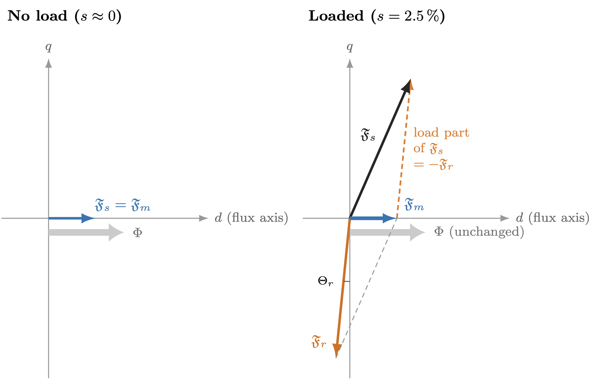
At no-load: Rotor turns with the field: so no slip, no rotor EMF, and no rotor current. The stator MMF is therefore only magnetizing.
When loaded: F_s + F_r = F_m = net MMF = the same as at no load. The rotor MMF sits almost on the q axis, and the stator adds an equal and opposite load part.
Translating between MMF and Current
The above MMF vectors operate in the d- and q-axis for magnetizing force and torque producing direction respectively.
From Part 1, we remember that MMF was a direct consequence of current: \(\mathfrak{F} = I N\).
Below, the MMF-producing currents are shown, but now the axes are voltage and current instead of voltage and MMF:
Same current scale in both panels:
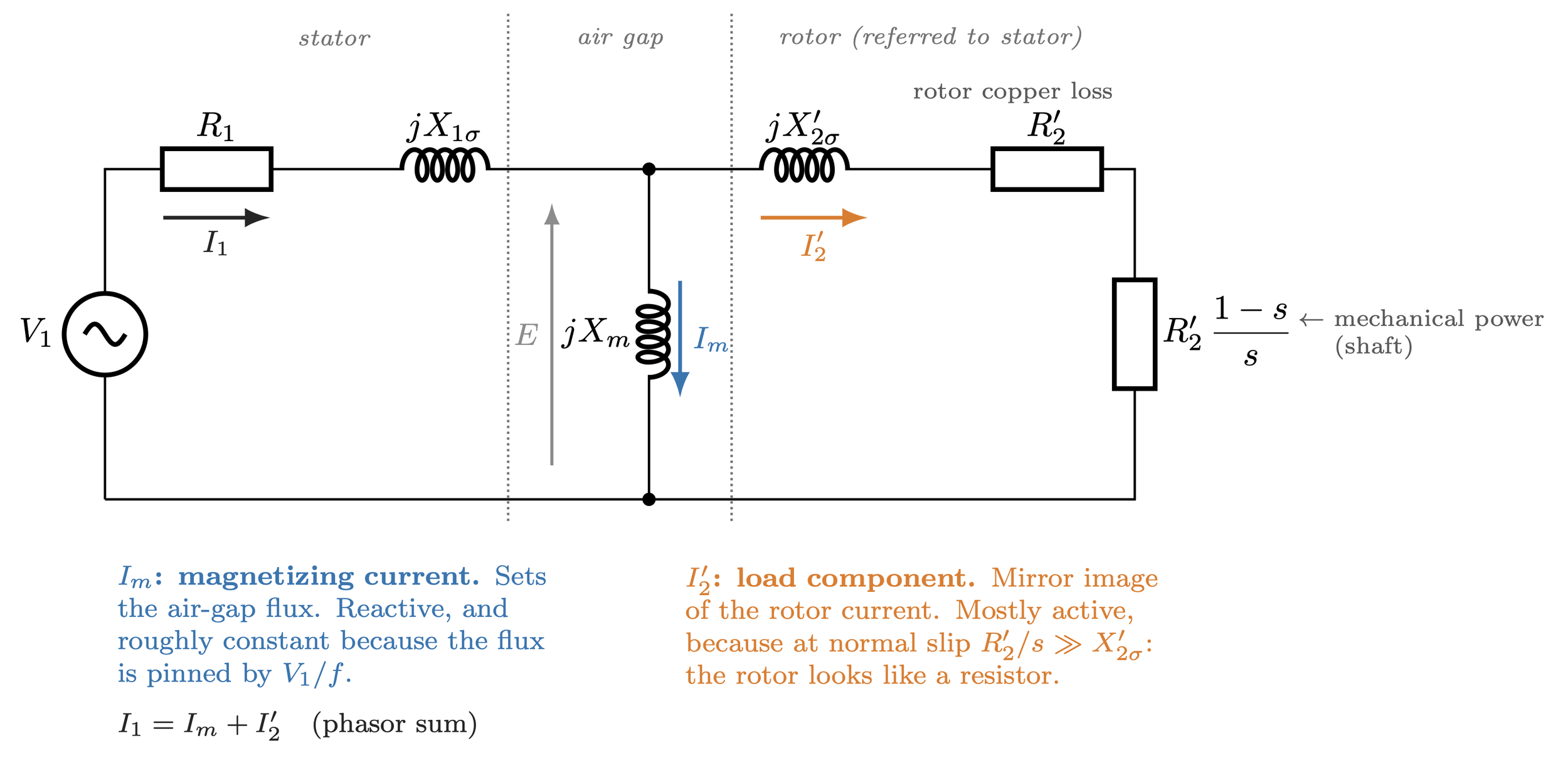
The magnetizing current, I_m (blue) is identical in both cases because the flux has not changed.
Everything the load adds, I′2, is pointing almost in the same direction as the voltage (in phase with). This means it is almost pure active power. The small tilt φ2 = arctan(sX′2σ/R′2) is the rotor leakage; it is the only reactive contribution that grows with load.
The above currents can also be shown in the motor equivalent circuit. Here we see the same three-way split between the stator (I1, black), the magnetizing (air gap, I_m, blue) and the rotor (I2, orange):
The currents and voltages in the rotor bars
This is where it gets interresting.
The rotor consist of a defined number of bars, in our motor throuhgout this article it has been 28.
As the stator’s synchronous field is rotating at the supply frequency speed, the rotor bars experiences this field as it passes by. The faster the rotor is rotating, the slower that stator field appear to the rotor (until they’re close to unity, and someone is forcing the rotor to rotate faster than the stator. This requires an outside force, the stator cannot accomplish this alone. Maybe I will write about this later, I have not decided yet).
Anyhow, because the stator field has a north pole and a south pole, bars too have induced voltage of different polarity. Come to think about it, anything else would be senseless. Imagine all rotor bars inducing the same voltage and sending the same current current in one direction, with no-one returning the current. Not possible.
Let us examine how this looks when looking into the circular machine
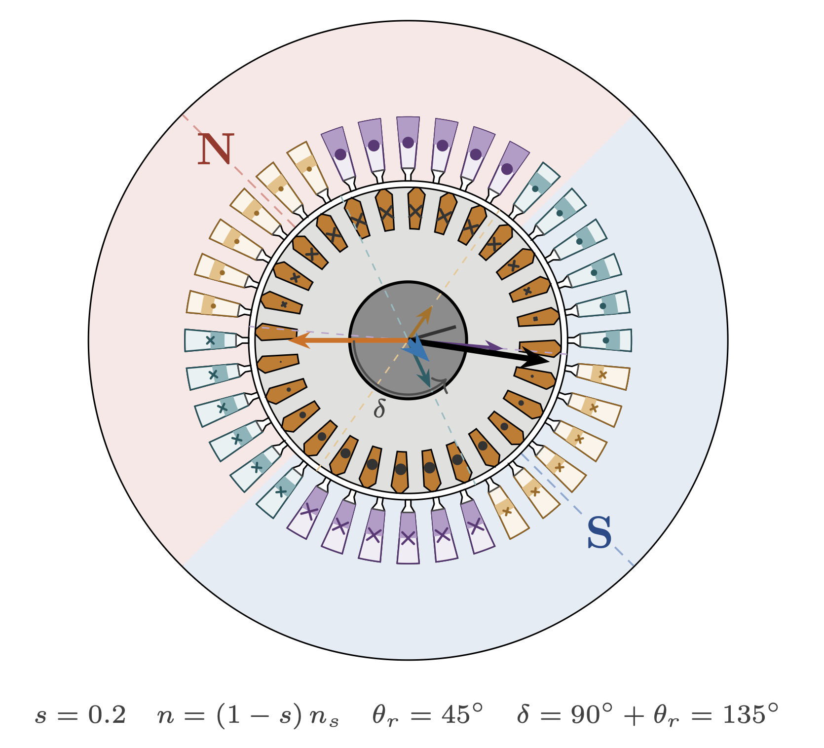
The slip of 0,2 (20%) is way above nominal loading, but the math in the figure is scaled by it, so I kept it so that the arrows are properly visible. 3% slip would be more realistic at high load, but then the arrows would be a mess to look at.
Now, I want you to pay attention to:
The blue magnetizing arrow. Contstant.
The black stator MMF and the orange rotor MMF, sweaping gently past the rotor bars. (You might have thought that the rotor MMF was locked to the rotor, but it is locked to the stator because the stator voltage locks the magnetizing MMF).
The voltage vectors are the ones growing and shrinking, their vector sum give the stator MMF
The stator slots and rotor bars: They indicate their current magnitude and direction by shading and growing dots and x-es.
Below is the full animation:
Let us “roll out” the rotor bars so that we can illustrate this with some figures and animations.
The circular stator and motor are cut open and rolled out.
On the top we see only the stator’s field (B-curve), with north and south pole designated as red and blue.
The bottom part are all the 28 rotor bars laid out side by side.
The orange currents in each bar are the current’s magnitude and direction, with an orange sine curve laid on top to show that they do indeed form a (somewhat staircase-y) sine wave.
The dashed red sine wave is the induced voltage in each bar. Induced bar-EMF is in phase with the B-field, while the current is lagging by \(\theta_r\).
Below is how this looks when the field is rotating and each bar has to take turn being induced in various amplitudes and direction.
For the next figure, I have ditched the rotor bars as rectangular copper colored parts and substituted them with the more common version found in the litterature:
Here, each bar are represented by a circle with an inner dot or x, depicting which way the current is flowing in each bar. As always, dot is current coming out of the page, x are the ones heading inward into it.
Four different aspects affecting the rotor bars, shown rolled out
This is a vertically stacked figure where the same instant is shown in four different figures (A-D) on top of each other on the same axis which represents one full revolution of the rotor, 0-360 degrees.
A: The 28 rotor bars are induced with voltage by the blue B-field in the air gap
B: The resulting bar currents in the very same bars
C: The resulting rotor MMF based on the bar current (behold the staircase-y sinewave)
D: The resulting force, as this scales with current and magnetic field
Below, an animation at 3% slip (s=0.03) is shown:
Here you see how each bar is induced as the rotor rotates at constant speed. The total force produced is the same, but how much force each bar is subjected to changes throughout.
Below we are animating this figure in a sweep where slip changes between 0.01 (low load) and 0,20 (close to break-down torque).
How slip affects the torque and rotor, will be explained shortly.
Notice the bottom panel, E. This is not a part of the 0-360 degree common axis panel A-D shares, but show how one rotor bar senses the rotating field as its relative speed (slip) is changing.
Torque characteristics
What we have seen below, is that:
As slip increases, relative motion between stator field and rotor increases
Increased slip therefore increases voltage induction in rotor bars
Higher voltage induction, more rotor current
More rotor current, more rotor MMF
More rotor MMF, more stator MMF
More stator MMF, more stator current
More statur current is more torque
In short: every time the rotor slows down just a tiny bit, the motor pulls more current to uphold the new slip.
But slip does not change by itself. Any given motor current can maintain exactly one slip speed. If load is added or removed, the slip changes and the current changes.
Imagine a motor operating a hoist, heaving a pallet of bricks off the ground. If the load is 1000 bricks, maybe the slip is s=0.01 or 1 %. Adding just one brick, increases the load and the slip, because the 1000 bricks load equal enough current for exactly 1000 bricks. You need more current to heave 1001 bricks, so adding it makes the rotor slow down by a tiny bit and you instantly get more current in the rotor and higher current to the stator to compensate.
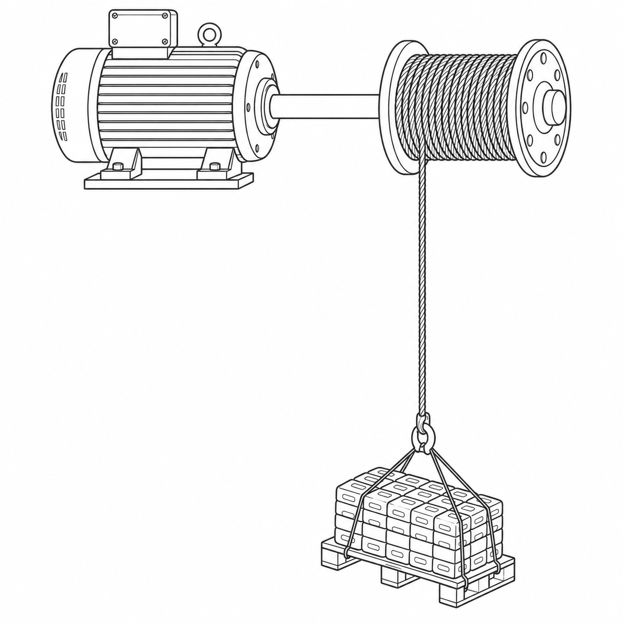
Even though I am not a certified slinger I can tell that this looks a bit strange, but I am not wasting my evening doing re-prompts to perfect it. And my own pencil sketch is far inferior. You still get the idea, right?
It would be a fun experiment really, keep adding and removing bricks to this hoist and see how the motor current changes.
But how many bricks can we add?
What determine the load a motor can take?
What happens as slip is increasing?
The limit to all of it, is how much current the stator windings can take before the insulation starts to smell weird, smoke and eventually break. By then, your motor is going in for rewinding.
The motor designer designs the winding wires, the winding slots and the insulation to supply enough current for the motor’s rated load. Well, duh, right?
This design point may put the rated current at slip around 3-5%, but the machine can handle a lot more slip than that. Just starting it exposes the machine to 100% slip, right?
To better understand the relationship between torque and slip, I have created yet another animation.
Now we can see the MMF vectors on the left and the well known slip/torque curve on the right.
Pay attention to that upper right panel, too. It shows that the rotor resistance is constant (in reality it changes slightly with temperature), and that rotor inductance changes with slip. This is the rotor leakage which tilted the I2 current slightly off 90 degrees earlier in the article. (note add phi_2, angle).
But the most important aspect of the animation is that it shows why the maximum torque is at 45 degrees rotor angle. Follow the red dot moving on the vertical torque axis on the left: As \(\mathfrak{F_r}\) is increasing, it grows on the quadrature axis, but after 45 degrees, it banks back toward the flux axis and torque goes down.
This aspect was also shown in the bottom power curve above (panel E): When slip is close to (but not quite) 1, only positive power is generated. When slip increases, more and more of the power curve dips under the horizontal axis and add negative power to the average.
So what is happening?
\(\Theta_r\) grows with slip: \Theta_r = s \omega \frac{ L_r}{R_r}
The “power factor” of the rotor declines, the corresponding counter-action from the stator therefore also become more reactive.
Exactly how the leakage inductance of the rotor bars respond, can be affected by the rotor designer. By altering their depth and shape, the machine’s torque characteristics can be custom made, but most machines are designed to conform to certain NEMA design codes which almost dictate how the torque slip curve look. This is done to standardize induction machines across vendors.
Now, behold below:
And here are some NEMA-variations showing how the rotor bars influence the torque charateristics.
This is actually quite interesting, because it examplifies four different design tactics used to manipulate the torque slip curve over the slip range.
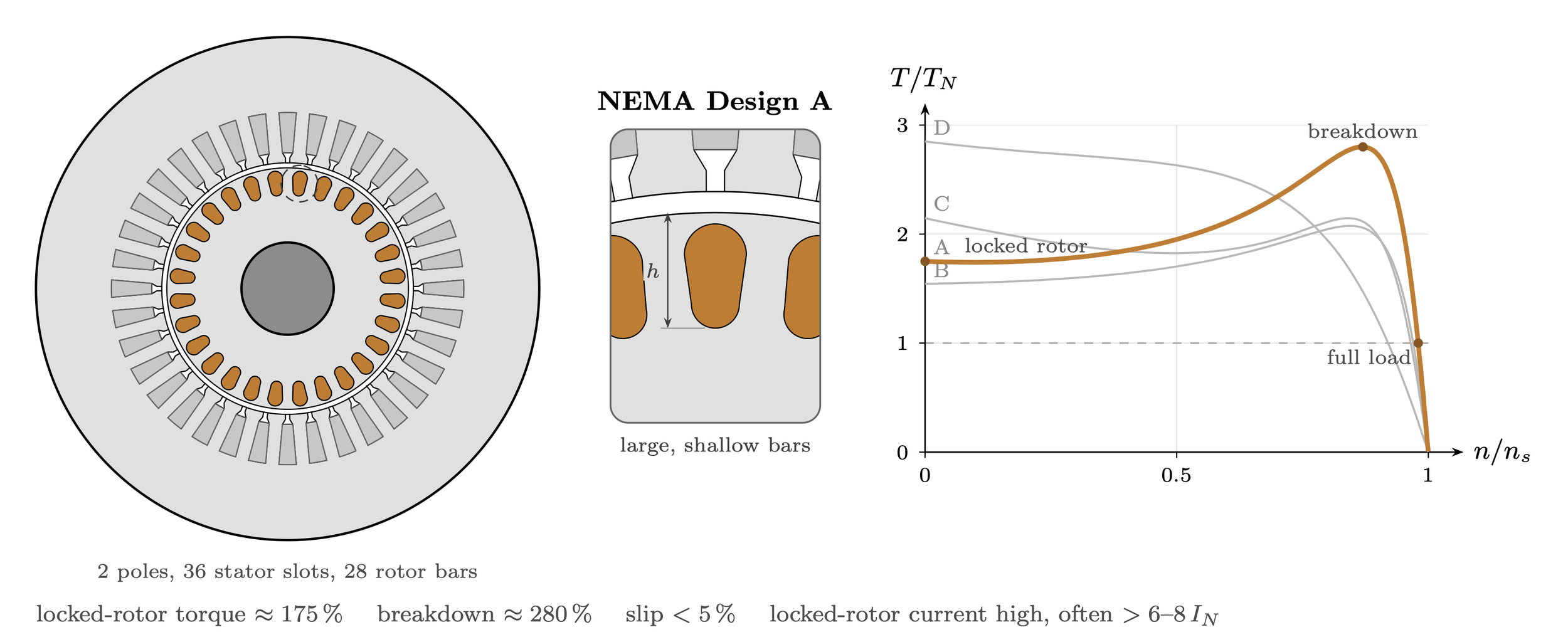
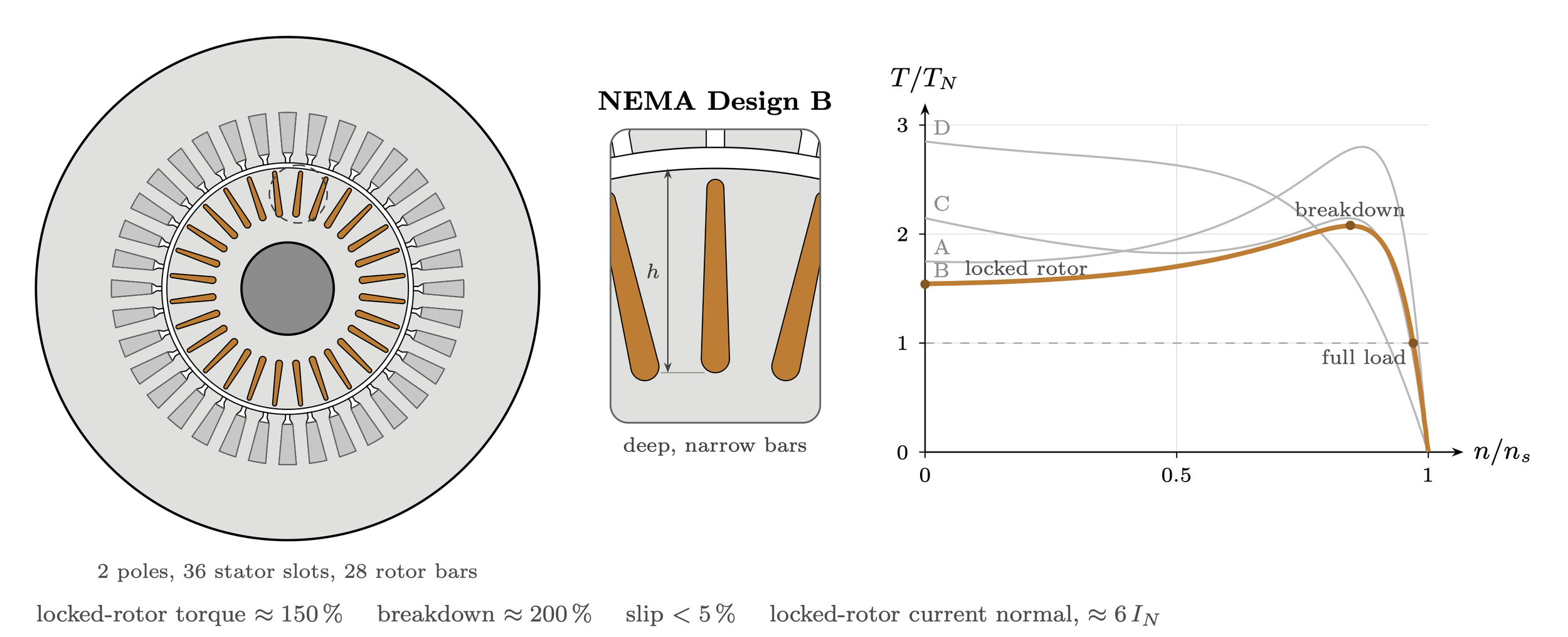
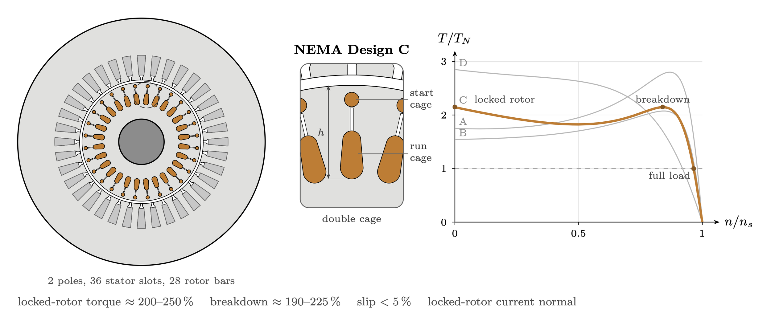
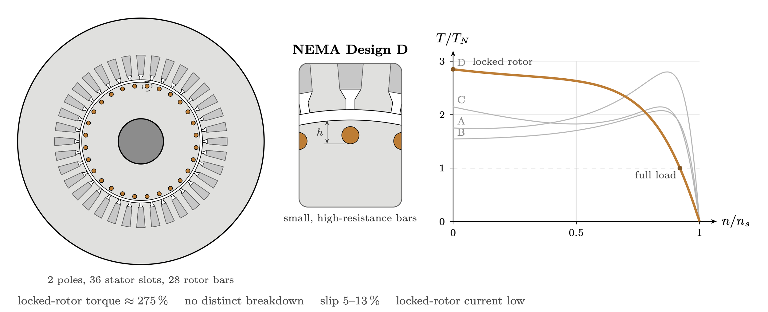
NEMA Design Code A:
Summary: Bars: Large, shallow, close to the air gap.
Torque effect: Highest breakdown torque, low slip, high starting current
Large bar cross section gives: low rotor resistance, low slot leakage across speed range.
When loaded, low rotor resistance means lower rotor losses and small slip
Low leakage inductance also results in the highest break-down torque of the four classes.
Low resistance also results in high starting currents, but only “normal” starting torque.
NEMA Design Code B:
Bars: Deep and narrow.
Torque Effect: Skin effect gives normal starting torque at about 6× rated current;
The “general-purpose” design.
During start (s=1): The leakage flux in the slot links more to the bottom of the bar than to the top.
This causes current to “crowd together” in the top of the bar, toward the air gap.
The effective resistance increases because only the top part of the bar is used to conduct current
As slip decreases during acceleration, so does the leakage flux. Current now occupies more of the bar.
At nominal working area, current spread out over the entire bar, lowering the resistance and losses
In this article, the rotor bars are a trapezoid (reaching r=1.05), this is close to NEMA B.
NEMA Design Code C:
Bars: Double cage (small outer bar, slit, large inner bar).
Torque effect: High starting torque, a dip, then a breakdown hump.
Two cages in one slot (!)
The smallest outer bars have high resistance and low leakage. Most of the starting current goes here and provide high starting torque.
Larger inner bars; sit behind a tiny slit, buried deep in the rotor: has high leakage reactance which prevents them to contribute at high slip (=high frequencies). This is reduced to almost nothing at low slip, so in nominal operating area the deep bars contribute a lot to low-loss torque.
High starting torque at “normal” starting current
NEMA Design Code D:
Bars: Small, high-resistance bars
Torque effect: Peak torque at standstill, 5–13 % slip.
Small bars, near the rotor surface. Often made of brass or a resistive aluminium alloy
Made to have high rotor resistance
Large slip-range in nominal working area
Does not have a break down torque, instead torque increases all the way from no load to stand still
important for hoists, elevators, and loads which accelerate large inertia
Price is that the torque curve is very soft, high slip at load and heavy rotor losses
Starting Torque Visualized
Imagine: You are sitting at the stator south pole; at the tip of the voltage space vector when the motor is connected to mains.
You can see the rotor bars, and at first - you are dashing past them in blazing speed. But as the rotor picks up speed, it seem to slow down as the relative speed difference decreases.
This is how it would look. (The torque-slip curve made for this animation is, well.. something between A and B.)
Breakdown Torque vs nominal Torque
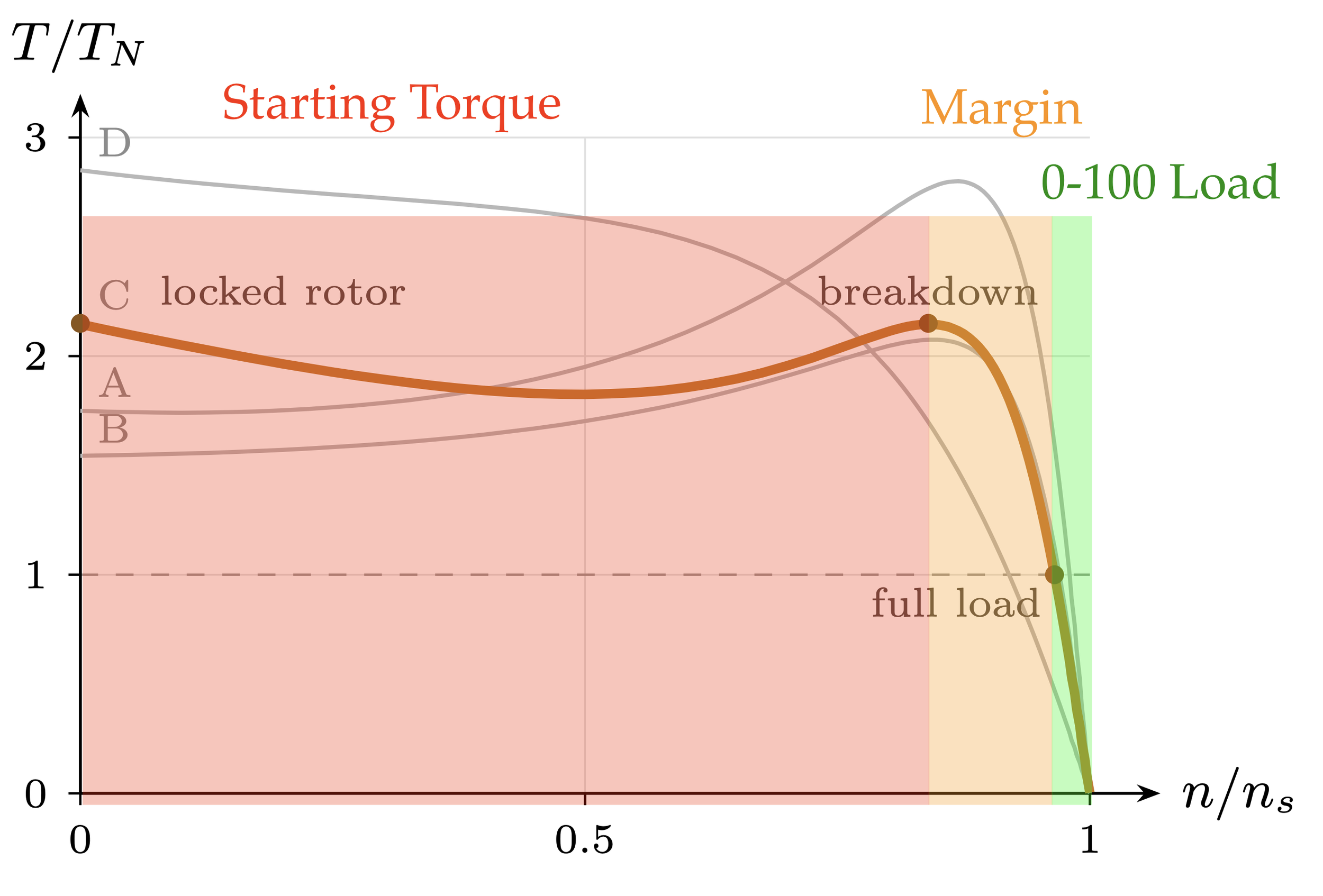
Starting torque from slip 1→ 0.20 (ish). Margin between 0.20 and 0.05 (ish again).
Typical loaded torque between 0.05 at full load and 0.99 at no load (ISH).
In the “normal” NEMA designs, A, B and C, nominal load is typically around 3-5% slip. Yet, their torque-slip curve show a peak around 20% slip - why not utilize that?
Margin.
If the motor operates at high load, it should be able to handle load fluctuations and sudden load changes without collapsing.
Imagine our hoist with bricks: It is heaving the pallet at max load, slip is 5 %. If someone dumped a few extra bricks on it, the rotor slows down, slip increase, currents increase, torque increase.
So, the motor runs a little warmer, but normally that is OK for shorter periods. Most motors have an overload rating for such scenarios.
The torque increase for each slip increase uptil around 20% slip.
If the nominal torque was 20%, any increase would increase the slip and reduce the torque. Adding a single brick to the load would make the motor reduce torque. The result would be that the load falls to the ground because its required torque was no longer met.
The margin between nominal torque and breakdown torque is therefore an operational safety margin.
Current distribution inside the rotor bar
In both NEMA design B and C, the depth of the bars affects how current is distributed radially.
Here we can see how:
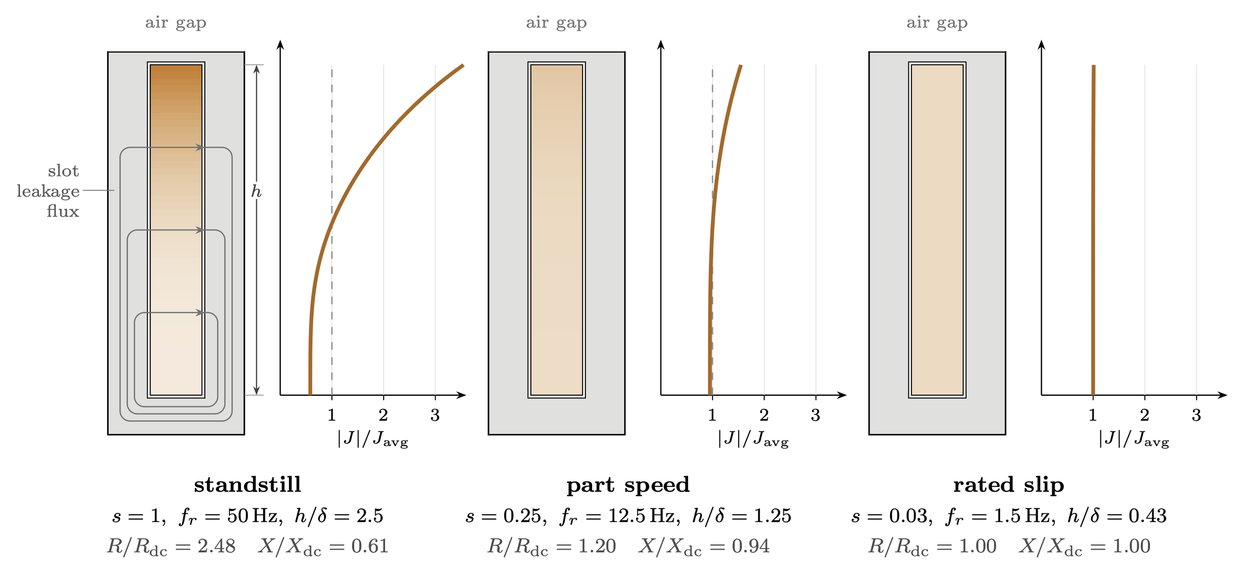
Current distribution in one rotor bar at three different loading. In all three scenarios, the total current is the same, but ho much of the bar it occupies vary. The color scale is shared across all three.
What this design do, is essentially to take advantage of the skin effect; at high frequencies, current is crowding at the surface. In this scenario, “high frequency” is the sensed rotor frequency relative to the stator. At stand-still, this is equal to the stator/supply frequency (i.e. 50/60 Hz for a directly connected motor).
So, the mechanism: the leakage flux which crosses the bar at a given height is caused by the current below it. This entails that the bottom of a deep bar is linked by much more flux than the top of the bar.
The bar essentially has more reactance (willingness to oppose change of frequency) in the bottom part than in the top, and starting a machine is asking it to change frequency a lot and fast.
Technically, the bar behaves as if it was only a skin depth δ deep, with a higher resistance and a lower leakage reactance.
This is how the starting torque of NEMA design B work: as the motor is running up, the rotor frequency falls while δ grows beyond the bar depth. When reaching the rated slip, current is filling up the whole bar area with almost pure DC resistance. Hence the low slip and high efficiency of design B.
Have I forgotten about the Field-Weakening now?
I certainly understand the question. We have been beating around a lot of bushes, haven’t we?
But what we have learned til now in this article, is how torque develops.
And guess what, it depends on the field!
The stator voltage sets the magnetizing field
That field is what induces the torque producing currents in the rotor
Lower field → lower torque.
Now you can see the whole chain of events leading to that fact.
In Part 3, we will be more practical:
How is field-weakening employed by motor drives?
What about permanent magnet motors?
Maybe a practical demo?