My name is Yngve. I don’t tend to stick my head out with strong opinions on the Internet. I have never really thought I had any interesting takes or opinions worthy of presenting. But recently it occurred to me that I do have one:
“Reactive power is seldom properly taught and rarely properly understood.”
And I think I can help with that. I also think that one reason people struggle to understand reactive power, is that it’s true origin is often omitted in classrooms.
Instead, reactive power is often explained as
«Power swinging back and forth in a power system»
«Free and useless power»
«The opposing side of the power triangle»
«The foam at the top of a glass of beer» (I particularly hate that one)
In my opinion, these explanations do not provide a meaningful understanding of the topic. It doesn’t even make sense, and I believe we deserve better. This article is my attempt at it.
Now “beer” with me, for you’re in for a ride to make perfect sense of reactive power.
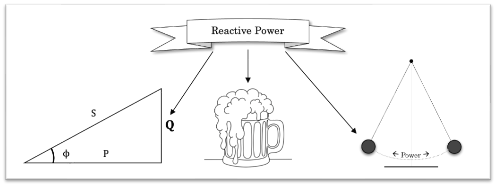
Some of the many forms of which reactive power can take - when explained poorly
Why Reactive Power Feels So Sneaky
After graduating in electrical engineering, the issue of reactive power became the most challenging for me to explain in an easy-to-understand fashion. This, of course, also meant that I didn’t fully understand it myself either.
My impression is that electrical professionals struggle with explaining reactive power in a way which makes people really grasp the concept.
Therefore, I decided to write this article hoping to formulate both an easy-to-explain and easy-to-understand analogy. This analogy would make reactive power, inductances, capacitances and their effect on both electrical circuits and the power system feel familiar, almost obvious.
I am stressing this point because I believe that to truly understand engineering concepts, it is not enough to understand only the equations. You must be able to mentally simulate how components interact with one another. That is, to be able to generate a mental model of mechanisms, manipulate them and understand how they interact with one another.
By doing this, one can build a deeper understanding by simply thinking about various setups – you don’t even have to perform real experiments anymore, your head can do them for you. It’s also a splendid way to find holes in your own understanding which you otherwise would be oblivious to.
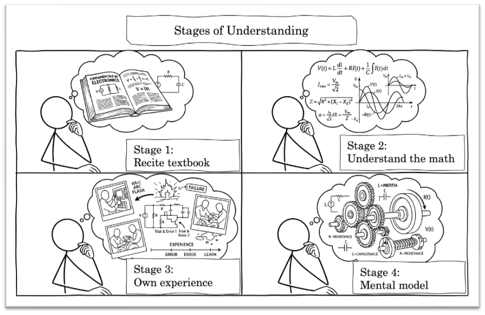
A typical engineer’s development trajectory
With that in mind (pun intended), the most difficult aspect in the field of electricity is its abstractness. This applies over the whole academic range of the field, from vocational introductory courses to university level (of which I have attended both and some in between).
But how should we design a mental model of phenomena which are invisible to us?
Mechanical engineers have cogs and wheels and suspension dampers which rotate, compress, bend and break. Civil engineers have beams, bridges and actual concrete. Our primate brains are very much accustomed to both visualizing and understanding such real objects and the forces acting on them. However, we have quite limited capability of understanding and visualizing magnetic fields, electron flow, self-inductance, voltage and so forth.
Electricity is generally both invisible and inaudible. Some might point out transformer humming, but alas - that’s magnetostriction[1]. Even the fancy arcs are not really visible electricity – they’re simply hot, ionized air that emits photons out of sheer atomic drama as particles are excited, ionized and recombine. The arc conducts current, but it is not the actual electrons we are seeing.
We can often see the result of electricity, but the mechanisms behind are concealed for us.
[1] Check https://www.comsol.com/blogs/modeling-magnetostriction-using-comsol for a nice animation.
The Mechanical Adaptation
Consequently, to better understand concepts in electrical engineering, it is helpful to visualize some kind of physical equivalent your brain is familiar with.
During electrical engineering introductory courses, water flow and water pressure are typically presented as analogies for current and voltage. And they kind of work, at least in the beginning. When reactive components are introduced, however, water doesn’t cut it anymore. We need something new.
So here goes; I believe this set of new analogies can improve our understanding of reactive power, and power systems in general. Instead of water pressure and water flow, I have found that the fundamental electric components can be shifted entirely into a mechanical domain and still maintain their properties and effects on one another.
The electrical and mechanical domains are surprisingly analogous:
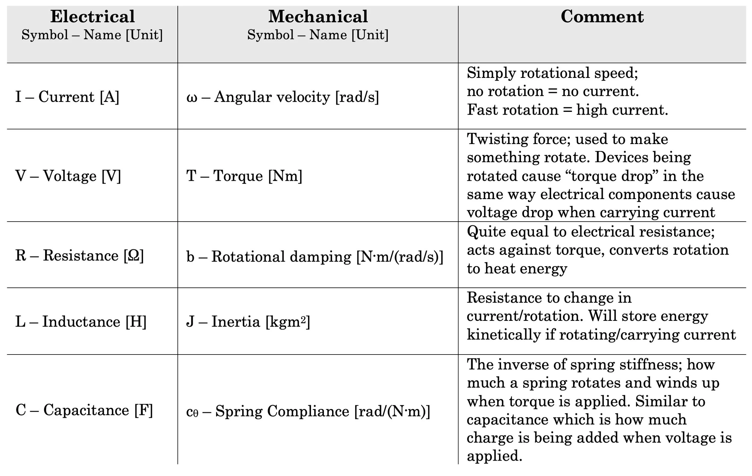
Someone did a ctrl-c ctrl-v when deriving the electrical fundamentals
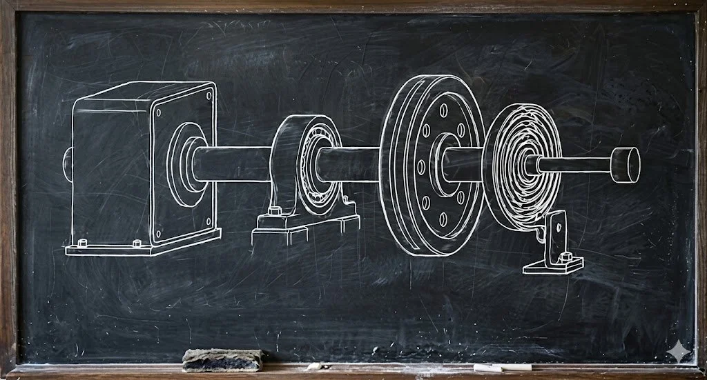
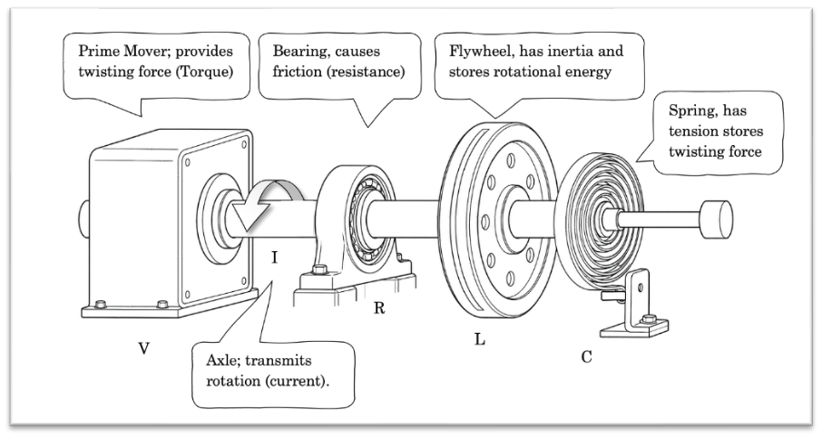
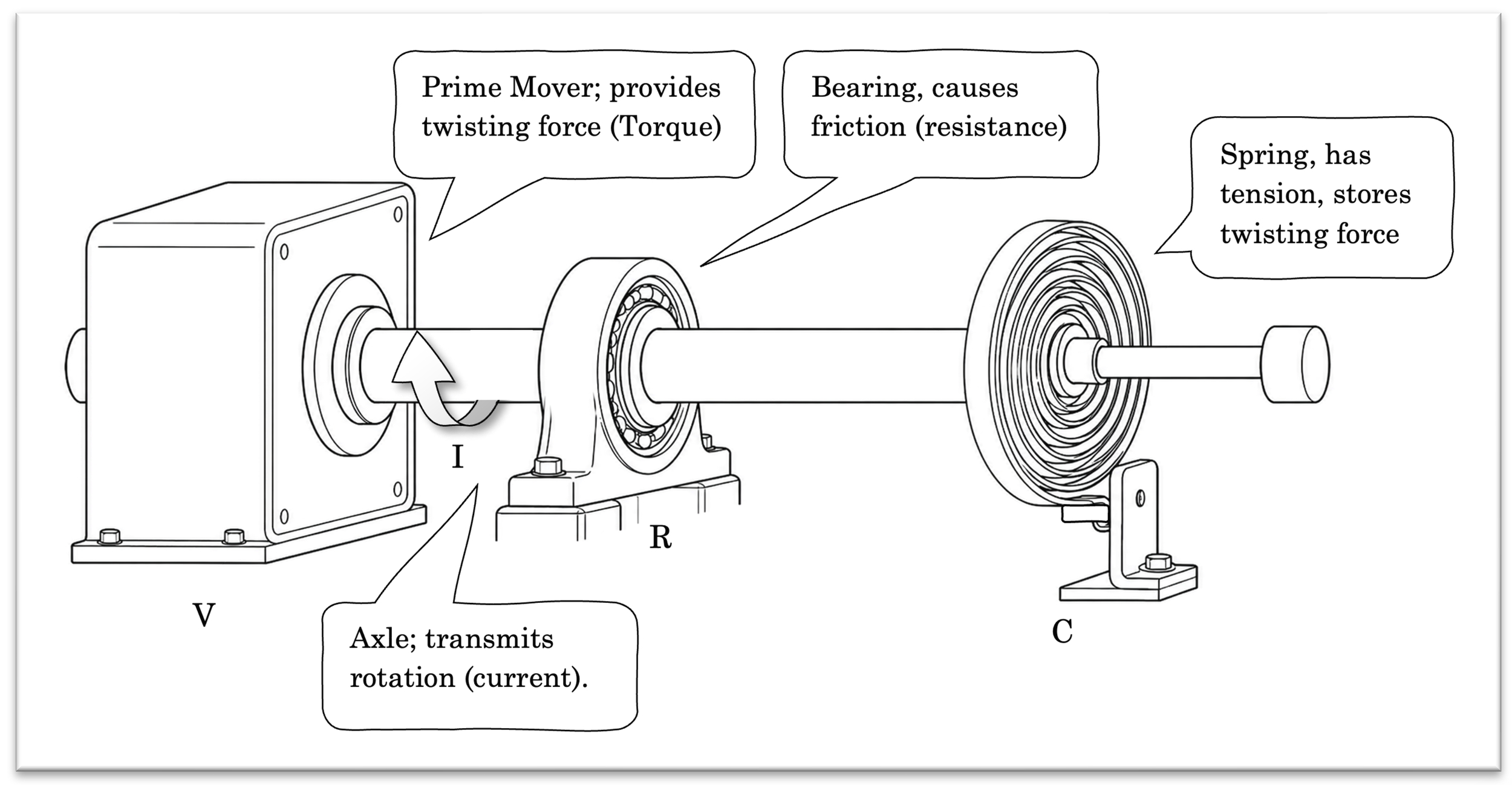
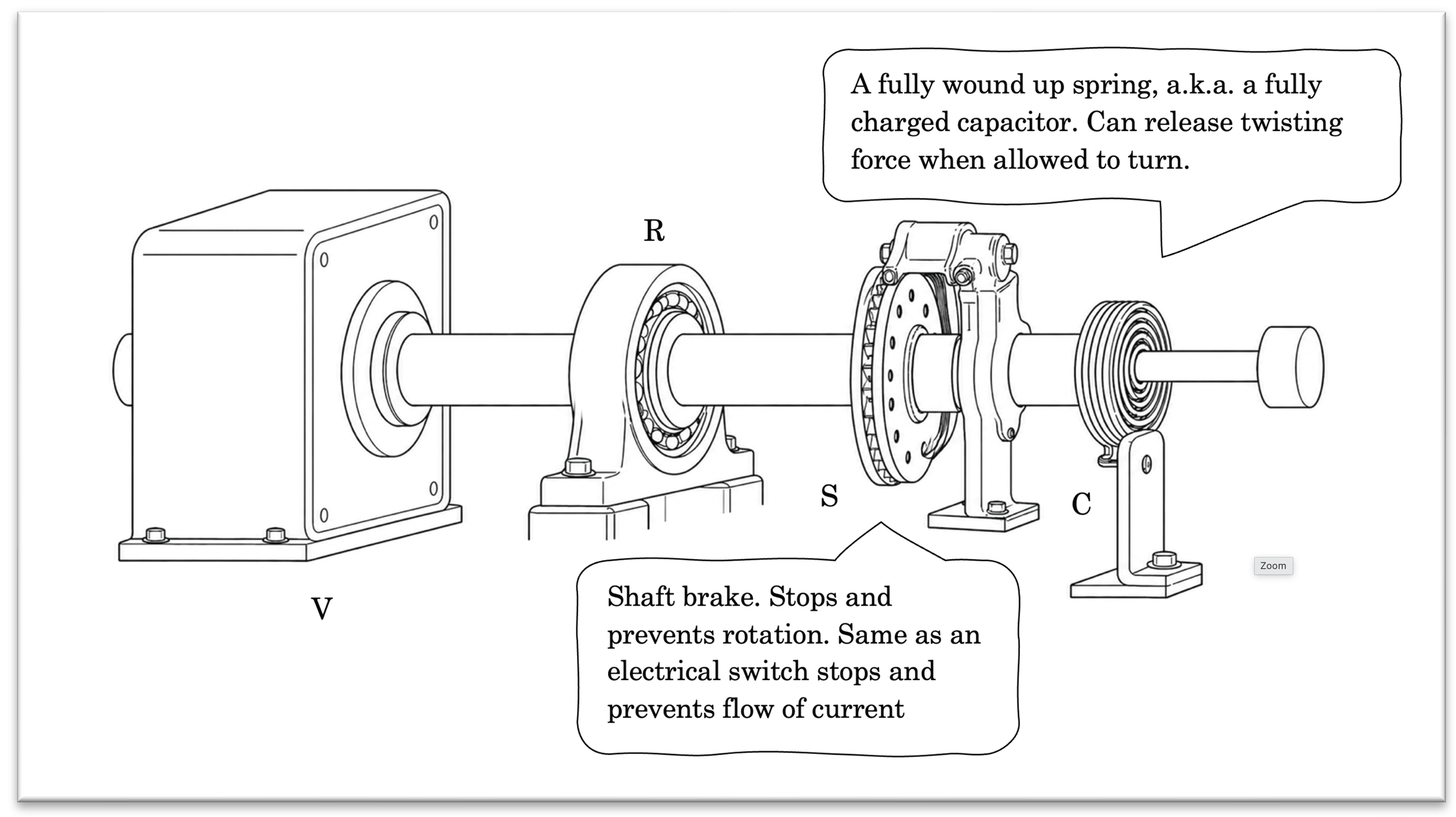
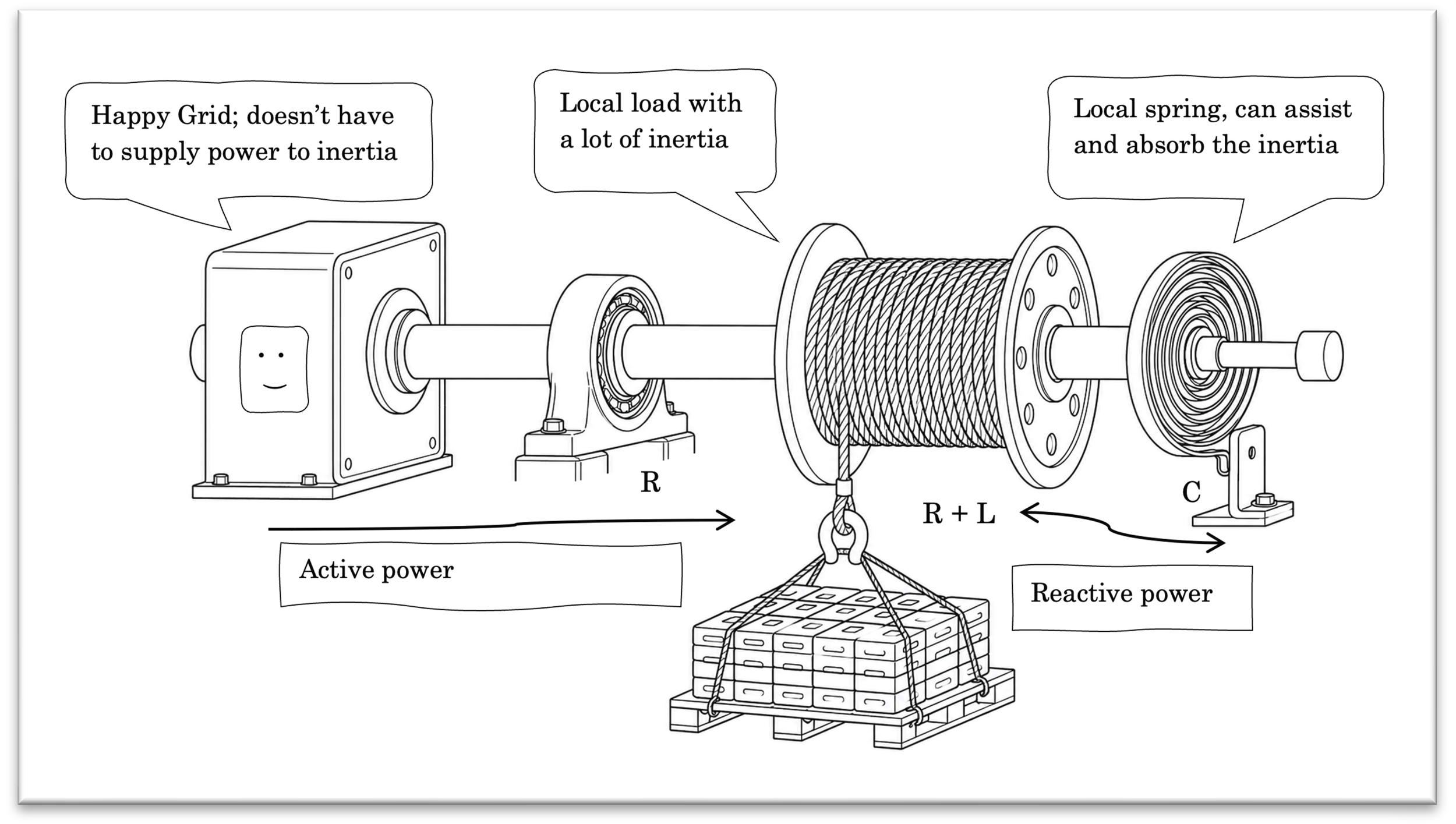
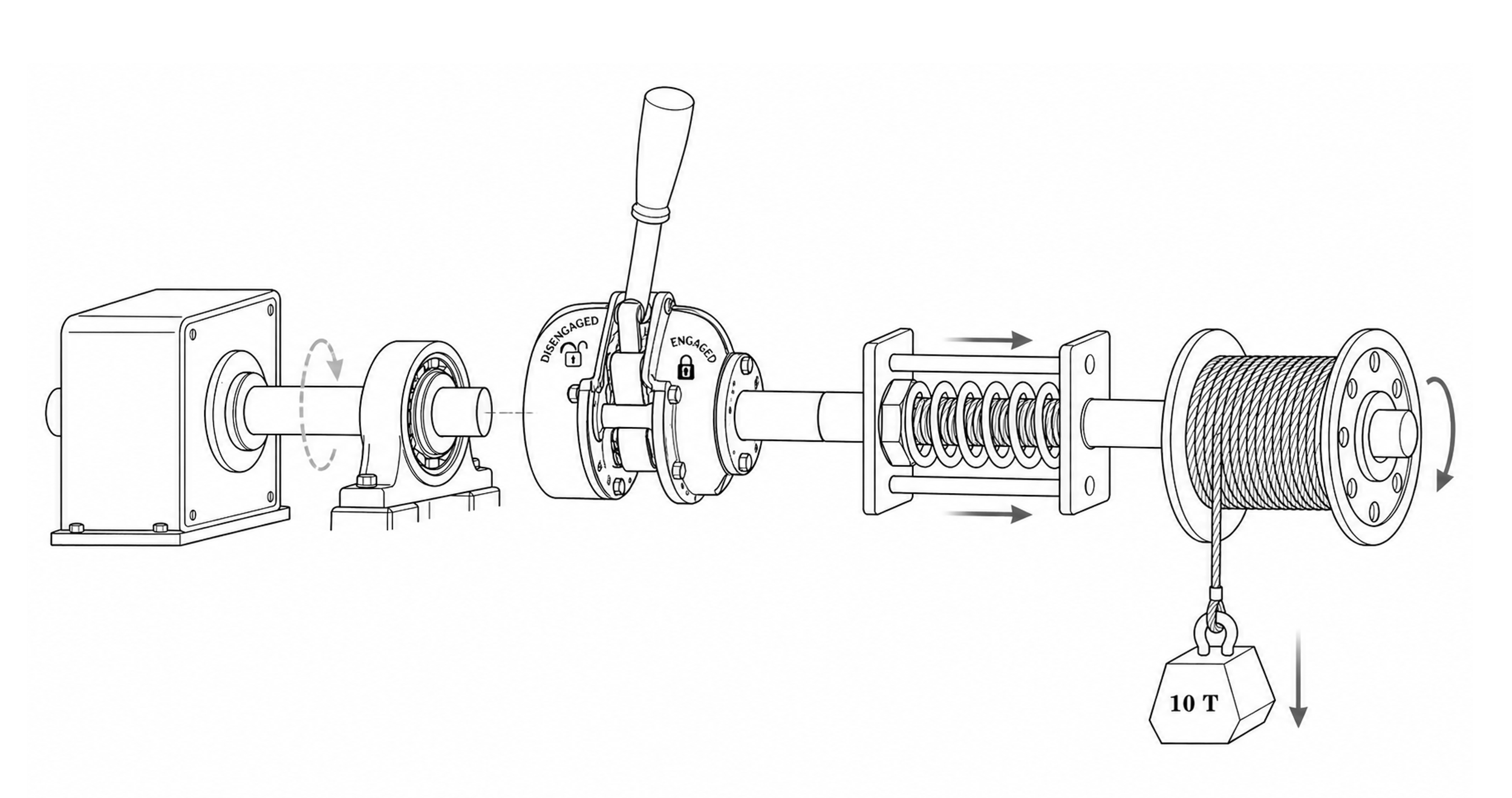
So how does this analogy look? Below I have converted a simple series circuit consisting of a voltage source, a resistance, an inductor and a capacitor to their mechanical equivalents:
This should be an aha-moment
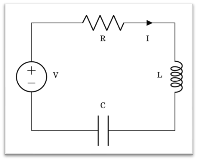
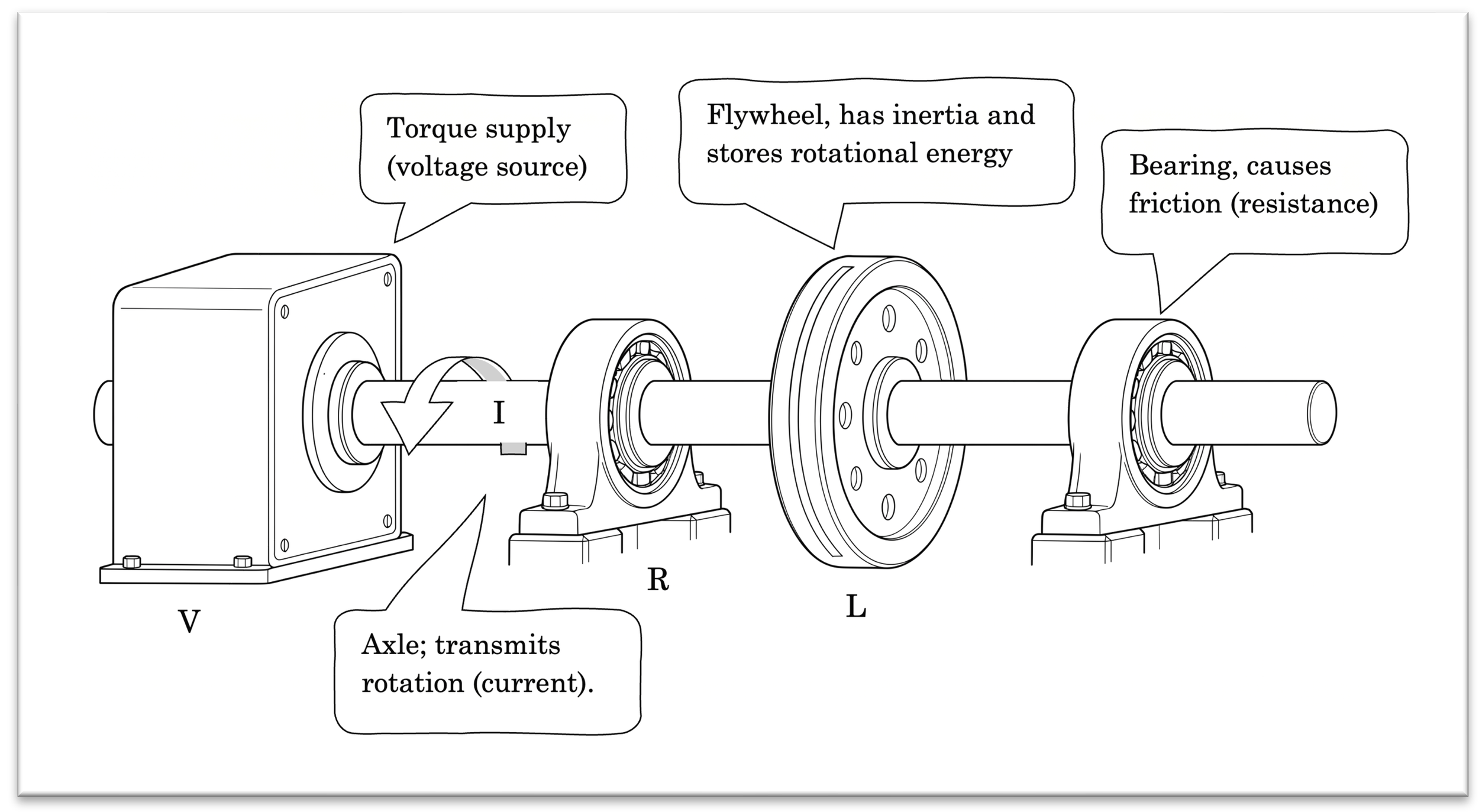
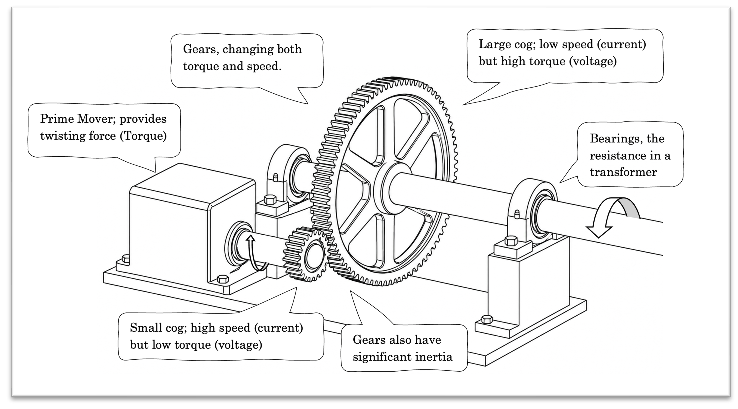
The electrical equivalent
The voltage source is a prime mover supplying torque (twisting force) to all components; it could for instance be a motor or another device generating torque. It is important to understand that this torque supply does not provide a fixed speed (that would have been a current source). Instead, the actual angular velocity this motor supplies is dependent on the resistance it feels. Low load = high speed, high load = low speed.
The bearing acts as a resistor. It opposes rotation and torque is needed to overcome it, generating heat in the process.
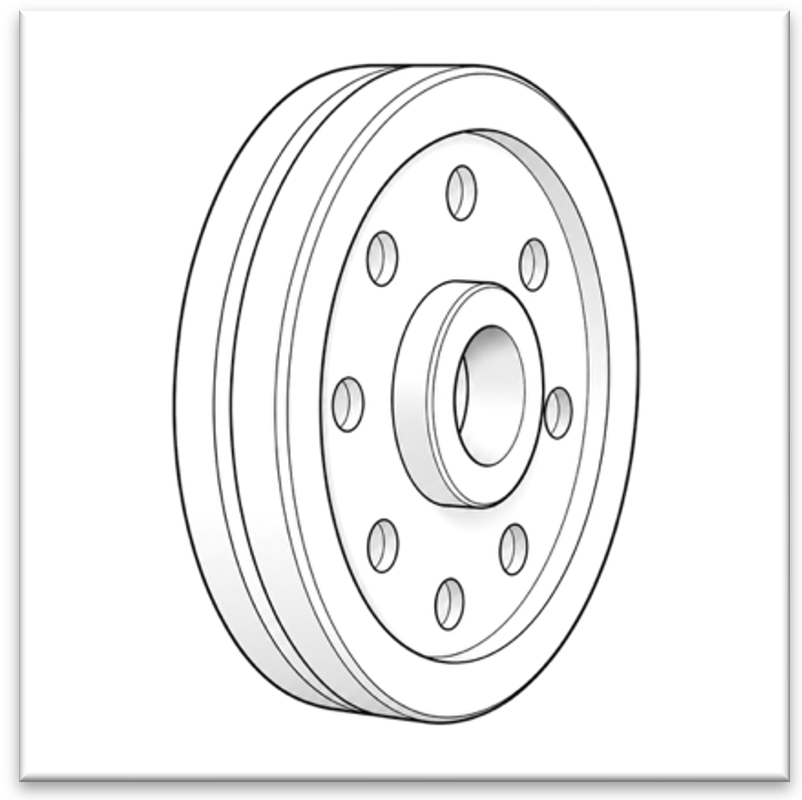
The inductor is a flywheel. It is slow to start, slow to stop and generally resists any change in speed. Stores a lot of energy in its rotation and inertia in the same way an inductor stores a lot of energy in its current and magnetic field. This is a kind of kinetic energy storage; motion is required to maintain it.
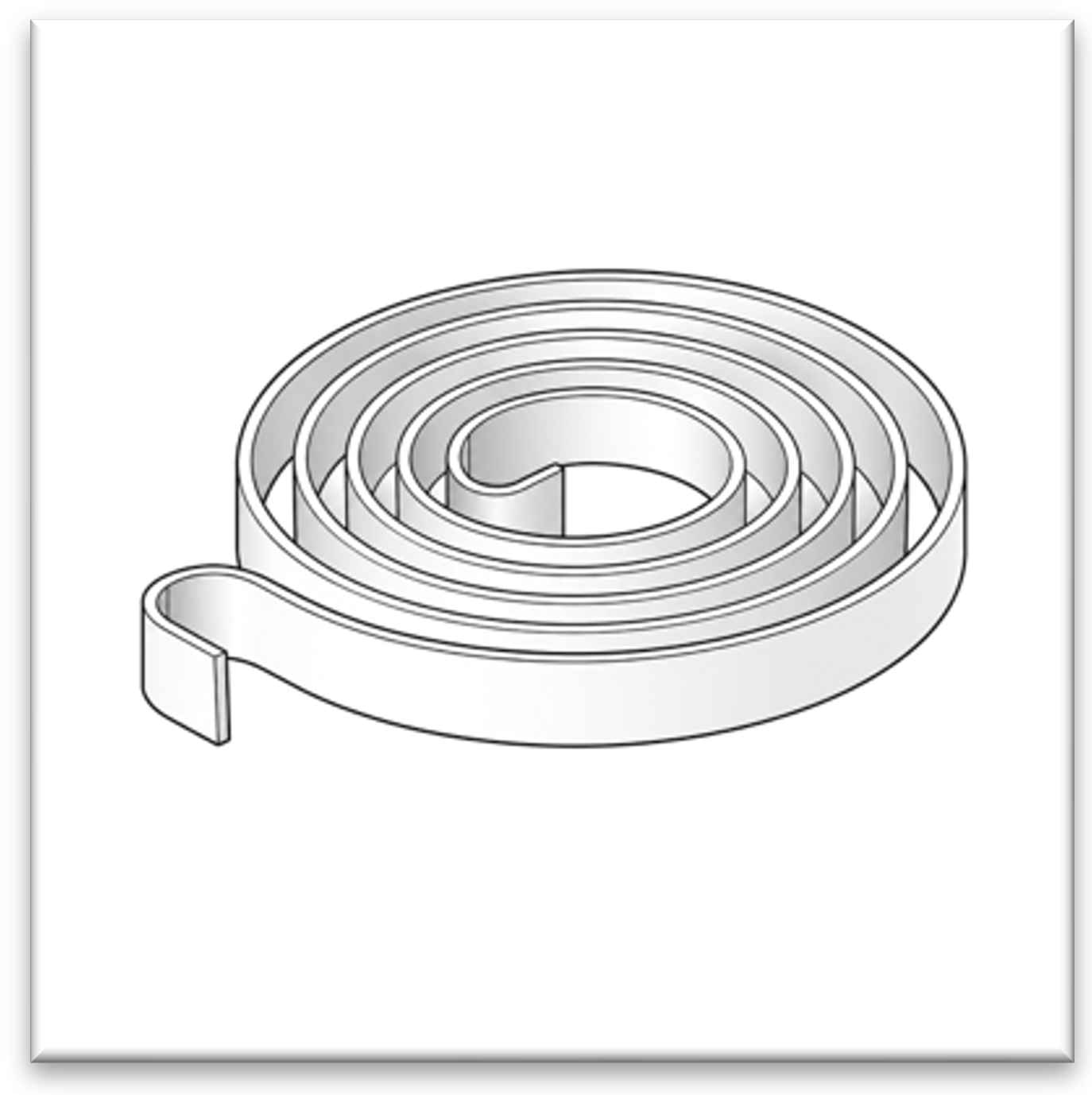
The capacitor is a spring. Since our analogy maps electrical current to rotation, I have chosen a flat spiral spring which rotates to compress, instead of the typical helix spring which requires linear motion to compress. The spring accumulates angular displacement (accumulated rotation) and stores that energy as wound-up twisting force. The capacitor separates electric charges onto its plates and stores energy in an electric field between them. This produces voltage across its terminals which can later drive current. As opposed to the kinetic energy based on flowing current, the capacitor holds potential energy in the static electric field; it can sit and wait until being used.
I have promised to explain reactive power, and you might be starting to feel impatient by now. But as reactive power is caused by inductive or capacitive components, it is essential that we understand those first. Once the behavior of these two components feels intuitive, reactive power becomes much easier to understand.
It’s like building a house, first we build the foundation (done), then we build the walls (next) and then we put the roof on top (last).
Afterwards we can sit on the roof together, laughing about how easy reactive power can be.
The Inductor
Let us start with the inductance. I find that to be the simplest one to visualize. It is also where all this started in my head after working for a long time trying to find suitable analogies.
We have learned that when applying voltage to an inductor, current is prevented from changing instantly; for instance, when you apply a step voltage across it, the current must build up gradually. The same applies when you are trying to pick up speed on a bike. Or push a heavy jack trolley. Or try to twist a large flywheel into rotation; you apply a lot of force… and movement comes slowly after. This is how inertia works.
In an electric circuit with inductance involved, that inertia is caused by its magnetic field: It is opposing sudden changes and must“charge” or “spin up”, depending on how you imagine magnetic fields.
The inductor is surprisingly similar to a rotating axle with a flywheel. They even share the same mathematical form as shown in the table below:
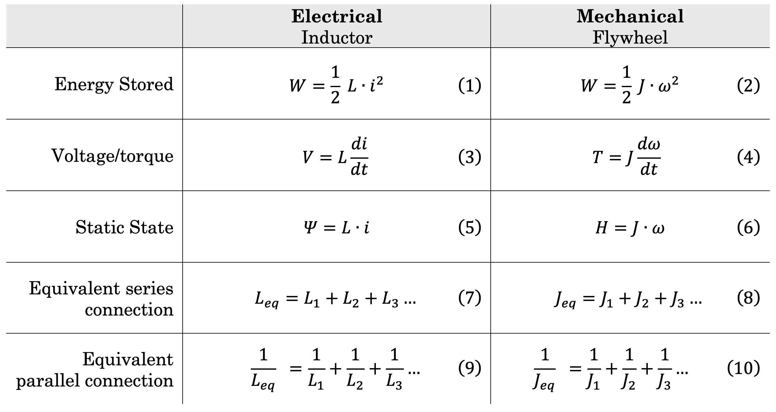
The copy-paste continues
Where (in pairs of their analogue counterpart):
L is inductance [Henry] – the inductor’s tendency to oppose change in electric current
J is moment of inertia [kg·m2] – the flywheel’s tendency to oppose change in rotation
I is current [A],
w (Greek letter omega) is angular speed (rotation) [rad/s],
V is voltage [V] – in some languages voltage is called “tension” which suits well.
T is torque [Nᐧm] – twisting force (which is a sort of applied tension, right?),
H is angular momentum [kg·m2 / s] – the spin angular momentum around the flywheel’s center,
Ψ (Greek letter psi) is the inductor’s total flux (or flux linkage) [Wb, or V·s] – the inductor’s electrical momentum as a “rotating” magnetic field,
di/dt is how fast current is changing,
dw/dt is how fast angular speed is changing
I will also add a note on the series/parallel connection:
A mechanical series connection causes same rotational speed for all components in series. When components are mounted on the same shaft, they share rotational speed but experience different torques, similar to how series-connected electrical devices have varying voltage drops but the same current.
A mechanical parallel connection is slightly different, however: The electrical parallel connection provides the same voltage (torque) to all components, but they will have a different current based on their electrical impedance. One possible mechanical equivalent would be the differential gear. This is the device most rear-wheel-drive cars have between their rear wheels. It applies related torques to two branches while allowing different angular speeds[2]. Those who have driven a car with a differential gear have noticed how a wheel on slippery ice will spin while the other wheel on ice-free asphalt almost doesn’t rotate at all. They have the same torque, but because their friction is different, the branch with the least friction gets the most rotation. That would be similar to a low resistance branch in parallel with a high resistance branch; most of the current will choose the easier path.
For the flywheel, the amount of energy it stores depends on its moment of inertia and how fast it rotates. A flywheel with no rotation has no energy[3], but a rotating flywheel can have quite a lot. An inductor with no current through it is harmless, but a large inductor with a lot of current going through it, can do a lot of scary things when forced to.
The voltage drop across an inductor (eq. 3) is tightly coupled with change in current; no change in current means no voltage drop, and no impedance (except for the resistance in the windings). If we disregard the always-present winding resistance, it becomes “invisible” to DC current as long as we are not trying to change its energy. This also means that you cannot increase or decrease its energy without changing the current. If you keep constant current flowing through the inductor, the energy will also stay constant. This is also apparent in equation 1.
For the flywheel, the torque equation (4) tells us that no torque is needed if no change of speed is required. Or vice versa; it tells youhow much torque you need to change the speed.
The inertia of a flywheel (J) and the inductance of an inductor (L) can be assumed constant[4] as it is a physical property determined by their design and construction. This means that both sets of equations mostly depend on the variables for torque (voltage) and angular velocity (current). I mean, there are not much else we can change with any of them.
We are now going to present some examples to really drill down this mental image of the inductor and flywheel.
[2] Other than its potential energy (it can fall on your foot).
[3] For those of you who have not played around with a differential gear, I highly recommend buying one of those Lego Technic car sets with a differential gear. They are surprisingly fascinating.
[4] “Ideally constant”, that is. Pushing too much current overloads the iron's ability to carry magnetic flux, changing its properties. High frequencies also create internal opposing forces in the iron, both of which cause the actual inductance to drop.
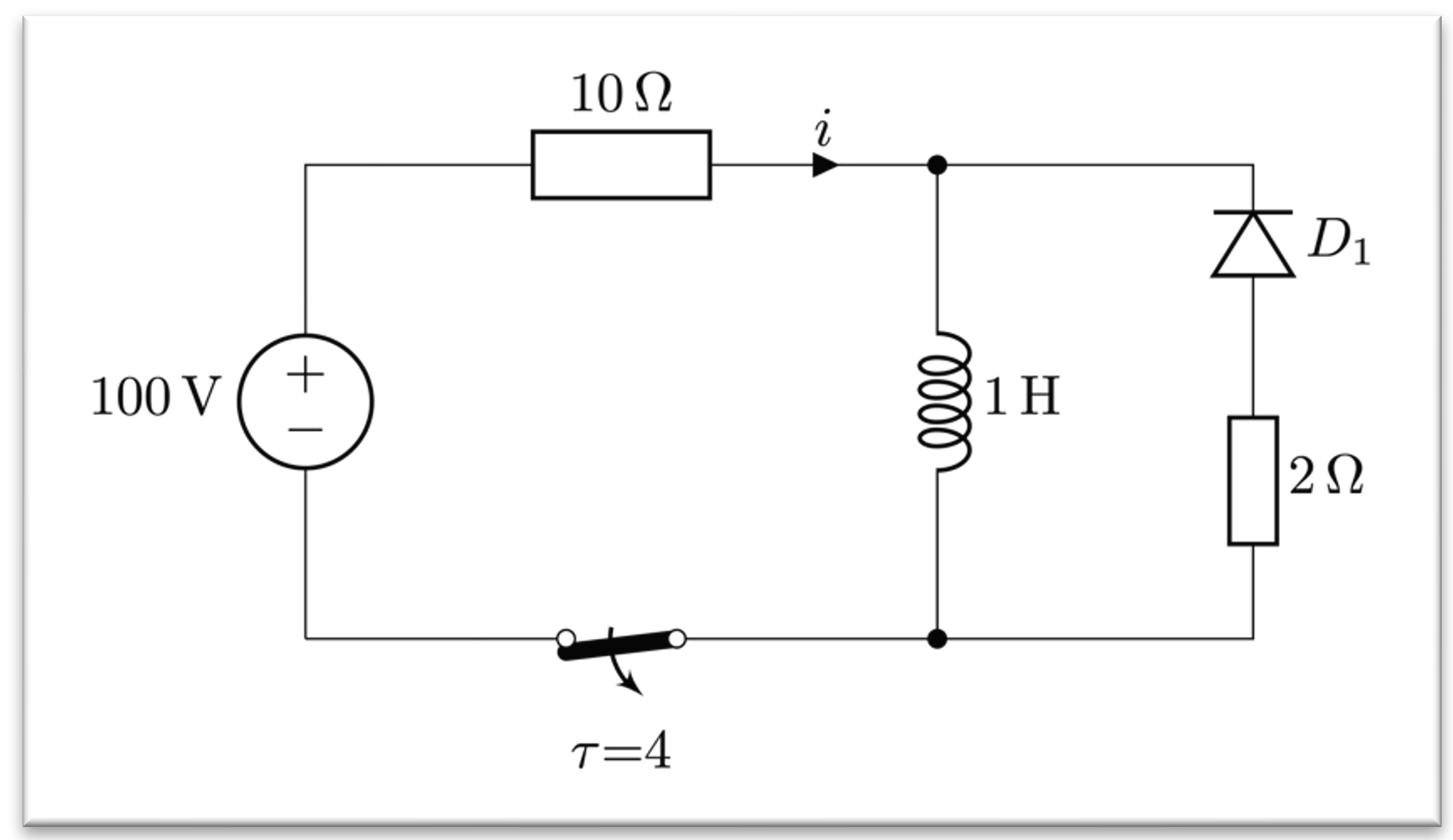
Charging the Inductor
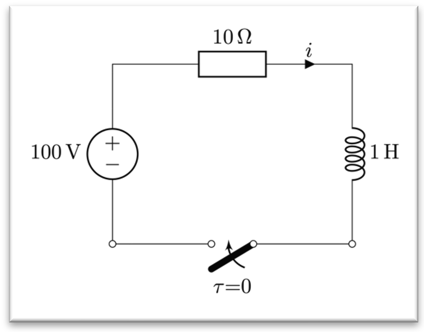
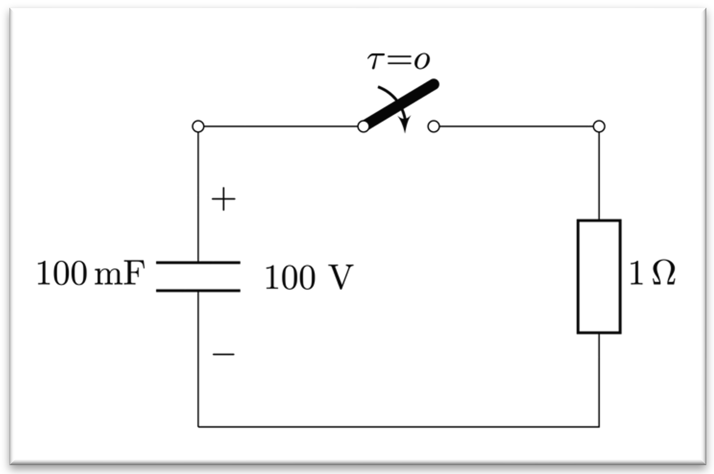
You apply voltage to an inductor in a simple DC circuit. Voltage is applied immediately, e.g. 100 VDC. What happens with the current? It grows steadily upward. As it does, the voltage drop across the inductor decays towards zero upon reaching steady stateaccording to equation 3:
\[ V_{L} = L \cdot \frac{di}{dt}\]
The voltage drop across the resistor looks inverse of that of the inductor; as current increases, its voltage drop increases too. That’s just Ohms’ law; \[ V_{R} = I \cdot R\]
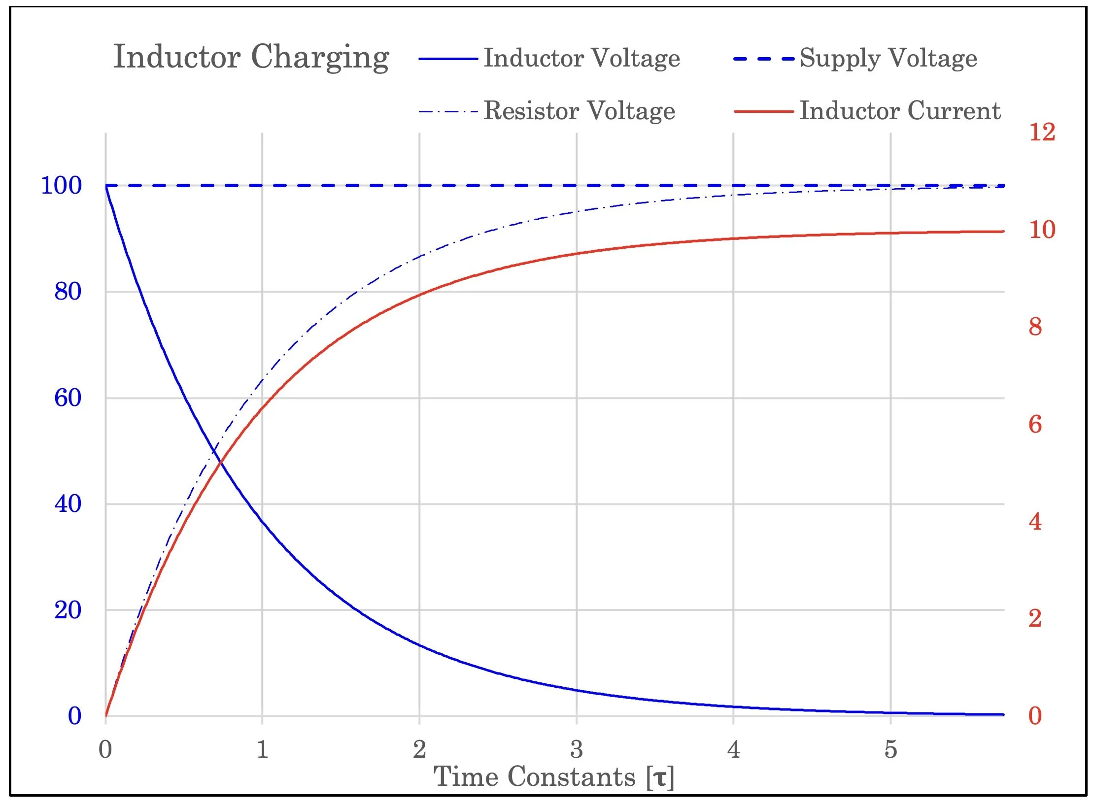
How an inductor circuit behaves when charging
The same mechanical circuit: a motor applies torque (twisting force) to a flywheel. Does the flywheel immediately and magically change to a different speed? No. It must accelerate, starting from zero, going through 1-2-3-4-5-6-7 revolutions per second to whatever speed it will reach given the motor’s applied torque.
Look at how inductive that flywheel is
As it accelerates, the bearing is also “spending” some torque. This is equivalent to the winding resistance’s voltage drop.
When the shaft has reached a steady state where the speed is constant there will be no twisting force needed to maintain the flywheel speed, only a small amount to overcome the resistance in the bearing.
Once no net torque is applied, the flywheel keeps its angular momentum. In the ideal lossless case, it would continue to spin forever. The inductor behaves similarly: In a closed loop without any resistance to dissipate energy (i.e. superconductor), the current would be maintained forever.
The stored energy in the magnetic field or in the rotating inertia cannot simply vanish.
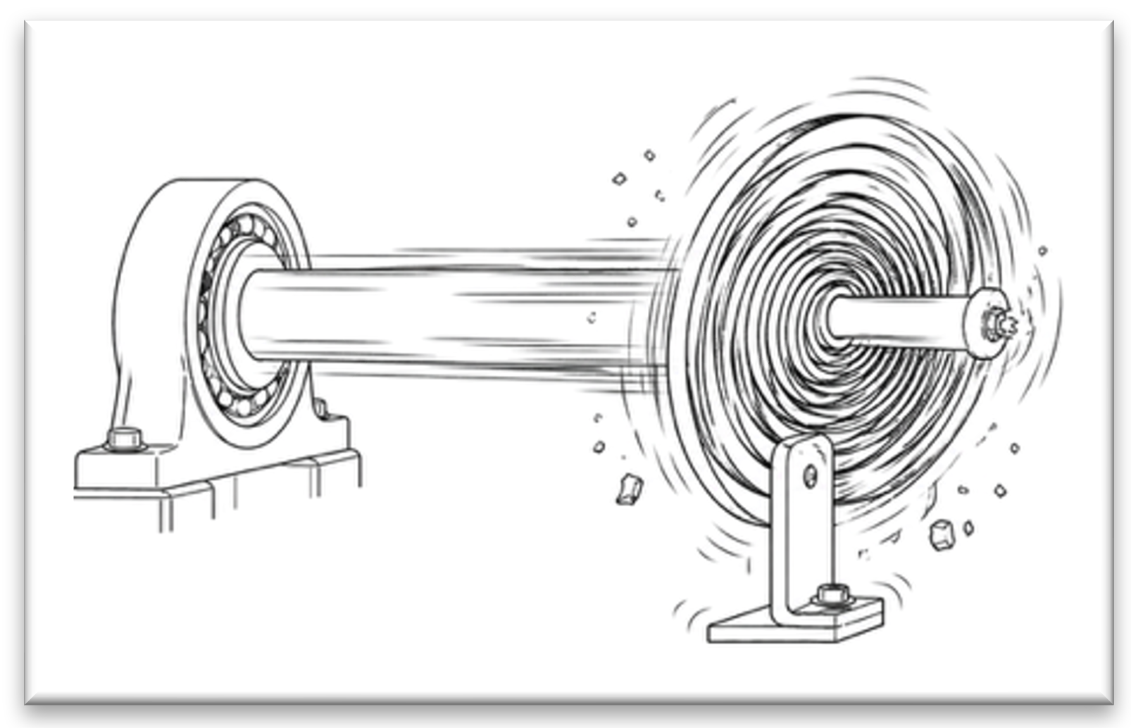
Opening an Inductive Circuit: The Gearbox Murder Scene
uh-oh. This is going to get ugly
Let’s do what we are taught not to do: open an inductive circuit.
What we have learned is that when an inductor is carrying current, it has stored energy in its magnetic field. That is why it takes time to get the current flowing in the first place; it has to buffer energy – just like YouTube has to buffer videos on a slow internet connection.
Anyways, in this case the current is already flowing. The inductor is happy at steady state with a steady current and the whole circuit is more or less blissful. So, let’s break it!
When you open the switch in a circuit, you are quite literally asking the current to stop.
You are actually asking the magnetic field to disappear.
You are asking a reservoir of energy based on the flow of current to simply disappear.
It is like asking a train to abruptly stop.
The universe has actual laws made to prevent exactly this [1].
But let’s try anyway, to see how the universe is trying to stop us:
As the switch contacts start to separate (imagine this is Hollywood slow motion), the switch is attempting to change its voltage drop from practically zero to a very high value. The inductor notices this as a huge current-braking influence; “someone tries to stop me and take my current” it would assume. But the magnetic field rushes to the rescue; in a last attempt to maintain its current, the field sets up as much voltage it can muster. Depending on the inductor and the voltage drop across the switch, the voltage spike (or “kick” or “back-EMF”) can be several orders of magnitude stronger than the original voltage source (remember equation 3? It works both ways).
So, the voltage spike is now starting to form a conducting plasma channel, an arc, across the air gap of the opening switch contacts. By doing this, the inductor provides a path for the current to continue flowing through the air gap of the switch and release its energy as heat over a brief period of time. By providing this time, energy can decrease to zero instead of suddenly change to zero. That is an important difference for the universe.
Now, this circuit massacre doesn’t play out any better in our mechanical world. As current is rotation, and opening a switch is the same as forcing current to zero, the mechanical analogy would be to force a rotating system to stop. Abruptly. I guess you can see where this is going, but let’s go through the motion:
The motor is spinning; the flywheel is happy, heavy and full of angular momentum.
Then some trainee with insufficient training accidentally changes gear to one that is welded stuck:
He is asking the axle and flywheel and all the little cogs in the gear to stop. Now.
The universe will. Not. Have. Any. Of that.
Speed cannot, will not, go from something to zero instantaneously.
This means that the gear which is welded shut must move. Or the shaft axle has to twist. Or bolts will shatter. Something has to give in order to provide some kind of de-acceleration time and relief for the flywheel’s speed and energy.
During this de-acceleration, the energy will be dissipated, and in this case – the energy will be used to move something that is not designed to move, break something else, make loud noises and probably generate some heat as well.
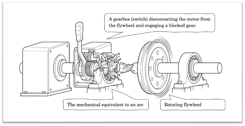
What. Have. You. Done.
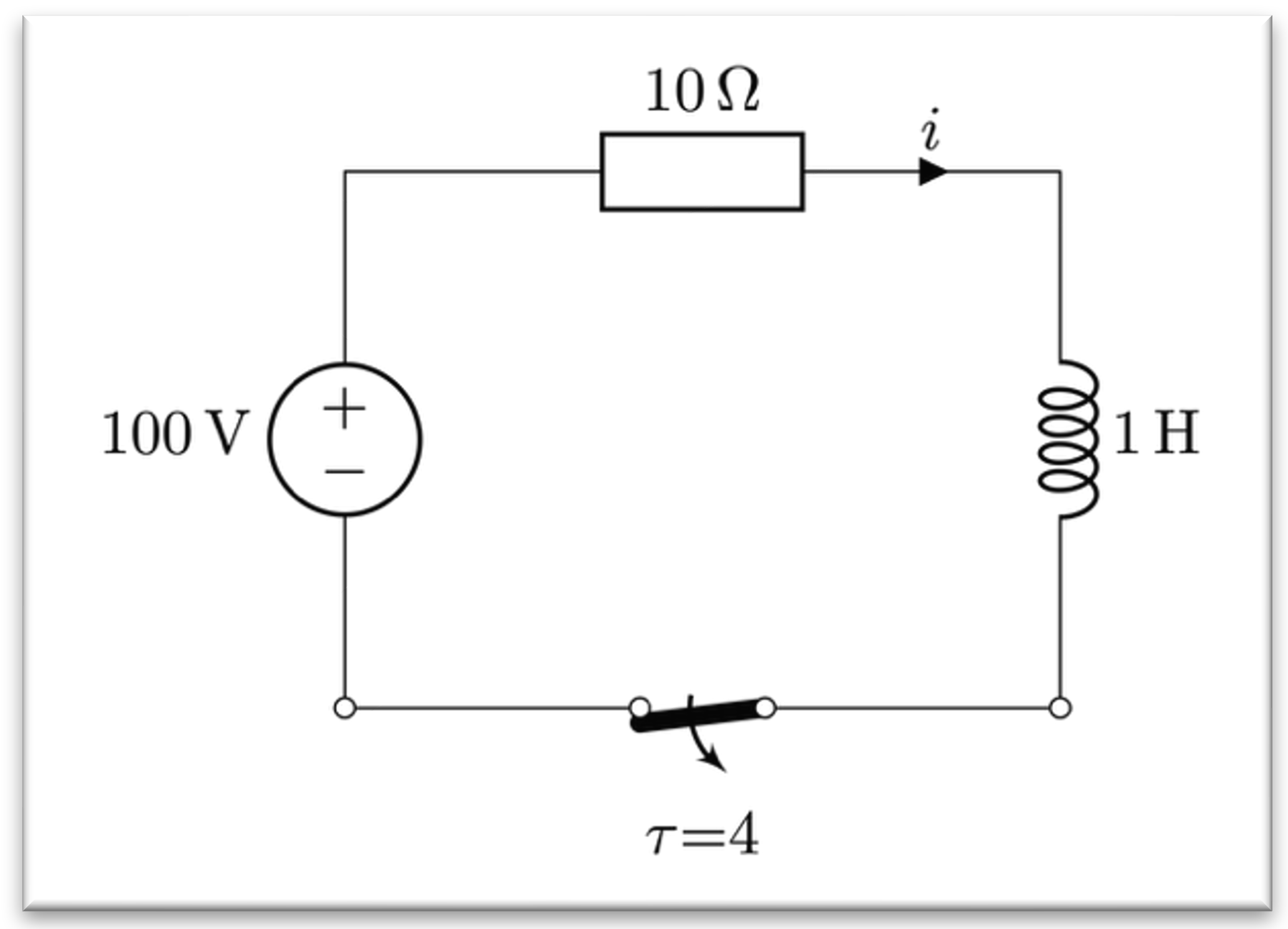
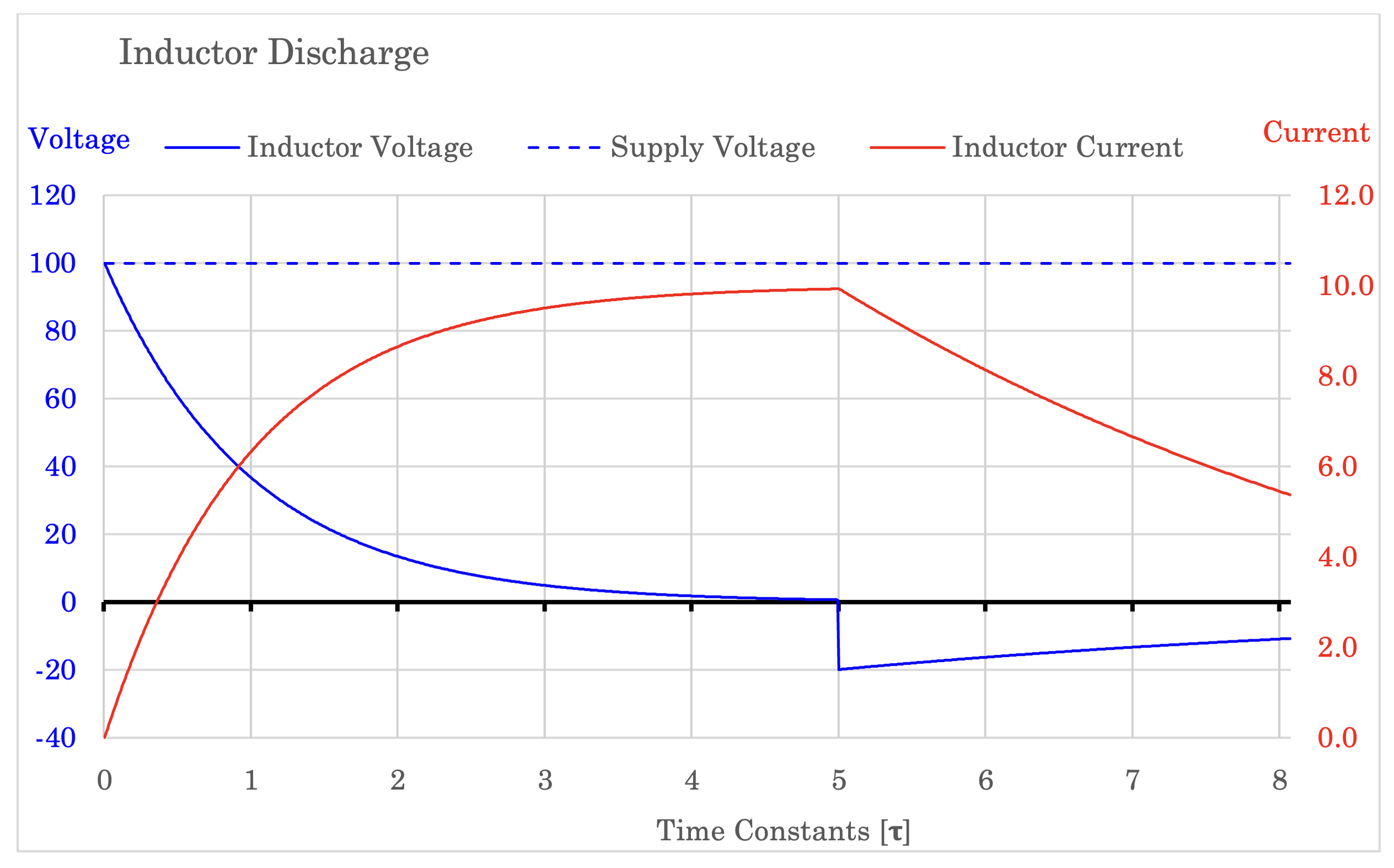
It doesn’t look so scary this way
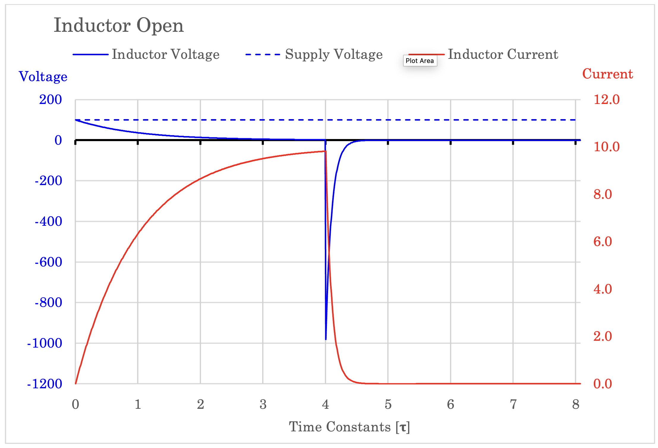
The graph is depicting the mechanical havoc as it would have unfolded in the electric circuit.
At 𝛕 = 4, the switch is opened. The change in current is now negative; it is decreasing. Fast. This creates a very high, negative di/dt value from equation (3) which again yields a high negative voltage. From the graph, it gets close to 1000 V, over ten times higher than the source voltage.
Author’s Note: when I was writing the numerical equations behind this graph, I defined the resistance across the arcing switch to 100 Ω, and I did that for two reasons: Firstly, the resulting arc plasma channel is actually quite conducting, hence it has a resistance. But the physics behind assessing this arc resistance is complex, nonlinear and very variable depending on several factors. Secondly, it made the axes of the plot fit nicely. I could as well have chosen 1000 ohms or even 1 ohm, depending on said physics. But 100 was the prettiest fit.
During the next few milliseconds, the energy stored in the inductor is spent maintaining this arc and the heat it generates (it is also worth noting that the contacts of the switch are easily damaged by this heat). As energy is spent, current is decreasing and this change (-di/dt) is less abrupt than the initial switch-opening shock, so the voltage spike from the inductor is decreasing until reaching zero. The mayhem is over, and only soot, arc-damage and a weird smell remains.
[1] Yes, Thermodynamics – I’m talking about you
Discharging the Inductor
“Safe and secure”
By now we have closed a circuit and opened (broken) a circuit. Both with quite different outcomes.
Now let’s change the circuit.
This is the usual, and polite way, to open an inductive circuit and is achieved by placing a resistor in parallel with the inductor, often through a diode so the path only conducts when the switch opens.
The purpose is that when the circuit is opened, the inductor’s energy has a place to go; to the parallel connected resistor which will discharge it in an orderly and controlled fashion. This prevents arcing across the switch as the inductor now can maintain its current for a short while when starting to discharge. The inductor is no longer forced to unleash its mighty magnetic field as a voltage spike.
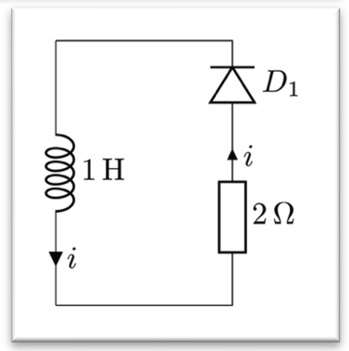
The remaining circuit as seen by the inductor current; much more pleasant.
In the figures, when the switch opens at , the inductor will “lose sight” of the entire left half of the circuit, leaving only the resistor and diode. Current will circulate in that loop until the energy has been fully depleted, converted to heat.
In a mechanical equivalent, it would be similar to engaging a brake to stop rotation. A brake is designed to dissipate energy as heat in the same way the parallel resistor dissipates the magnetic-field energy as heat. Much gentler, and the trainee can come to work the next day with his head high.
You can almost feel the parachute as the inductor current gently glides toward zero AGL.
So, halfway there! Next:
The Capacitor
Ignoring some tiny, vital, details, this spring actually resembles a real capacitor in some ways. That is a funny coincidence.
This fellow is the inductor’s opposite twin in so many ways. They are Yin and Yang; complementary forces in the electrical world. As opposite twins, the inductor and capacitor can play remarkably well together in a circuit. And sometimes not[1].
The capacitor works by separating charges; forcing the negative charges to one plate while keeping “positive charges” on the other plate. In metal conductors, it is mostly the negative electrons that actually move. So, in this context, the positive side can be thought of as an electron deficit rather than little positive particles flowing around the circuit. When charges separate this way, an electric field is established between the plates, and this appears as voltage across the capacitor terminals. It is important to know that there is a dielectric medium between the plates, so it will not conduct current. The moving charges is instead being pulled through the entire circuit from one plate to the other – not directly across.
In school, we learn that a capacitor prevents voltage from changing instantly; when you connect a voltage source to it, the current (or charges) starts flowing immediately. The voltage across, however, builds up gradually. In an electric circuit with capacitance involved, that delay is caused by the electric field: It is opposing sudden changes and must “charge” gradually as electrons move from one capacitor plate to the other.
In our analogy, current is rotation and we have established that rotating inertia is the same as inductance storing kinetic energy in a magnetic field. The capacitor, however, is storing potential energy in the electric field.
Ergo a mechanical device storing energy as torque we can use later. If it rotates, energy will either increase or be returned, depending on the direction of rotation. This voltage being built-up is similar to storing torque.
The capacitor equivalent is a flat spiral spring. This is the same mechanism used in traditional wrist watches or those pull-back toy cars. I chose the spring of two reasons: Firstly, because if it has been twisted, it really wants to twist back. Secondly because it stores torque-like potential energy which fits nicely in the analogy.
Righty tighty, lefty loosy
The way it works is that when the shaft is turning, the spring is being wound up and tightened; it stores twisting force. When released, it unwinds by turning the opposite way, returning the energy as torque and rotation. A short circuit would be similar to un-winding the spring with no resistance, releasing all the energy at once. Sproing!
Yes, I made a figure just for this.
To keep the spring from unwinding, we must prevent rotation. Electrically, that would be a switch preventing current. Mechanically, it would involve a brake.
The brake disk might be slightly over dimmensioned
If a charged capacitor was connected to a load, the flow of current from the capacitor would be influenced by the change in voltage inside it and by the charge remaining. There would be more current in the beginning than in the end of the discharge period.
A spring behaves equally: how fast it unwinds depends on the energy and torque stored in the spiral, and on the load attached to it. The release is strongest at the beginning, when the stored torque is highest, and becomes softer as the spring unwinds.
Further, the spring’s energy storage is a function of a) the mechanical property of the spring itself (what kind of metal is used, thickness of the metal band, how tight the spiral is formed etc.) and by the number of turns it has been twisted. The latter can also be seen as how much torque has been applied to wind up the spring. If you subtract any internal losses, that is the energy available to you when discharging.
The same applies to the capacitor: the amount of energy and voltage it stores depends on its physical properties (e.g. size of plates and type of dielectric material) and by how much charge has accumulated on its plates. The stored voltage can also be seen as the result of the voltage that was applied during charging, minus any internal losses.
The flat spiral spring and the capacitor also have a remarkably similar list of equations:
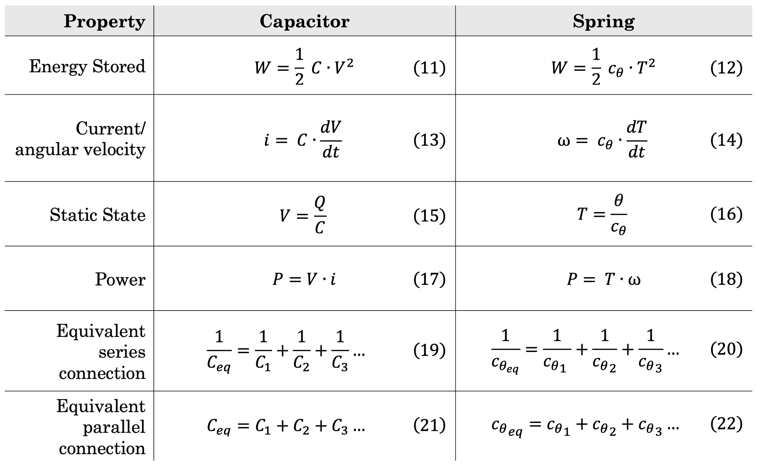
This is starting to get unnerving
Symbols explained below, ordered in pairs of their electrical and mechanical counterparts:
C is capacitance [Farad] – how much charge Q is stored per Volt applied,
cθ is the spring compliance – how much the spring turns (θ) per torque applied (𝜏)
(the term compliance is the inverse of the better-known spring constant usually denoted with k),V is voltage [V],
T is torque [N·m] – twisting force,
Q is stored charge [Coulomb], or Ampere-second [Aᐧs]
(not to be confused by the symbol Q in the power triangle, which is reactive power)θ (Greek letter Theta) is angular displacement [rad] – Stored twist/rotation in the spring,
i is current [A],
⍵ (Greek letter omega) is angular velocity [rad/s],
dV/dt is how fast the voltage is changing,
dT/dt is how fast the torque is changing
[1] Sometimes, resonance between them is desired and everyone is happy – other times, resonance creates a disaster and no one is happy.
Charging the Capacitor
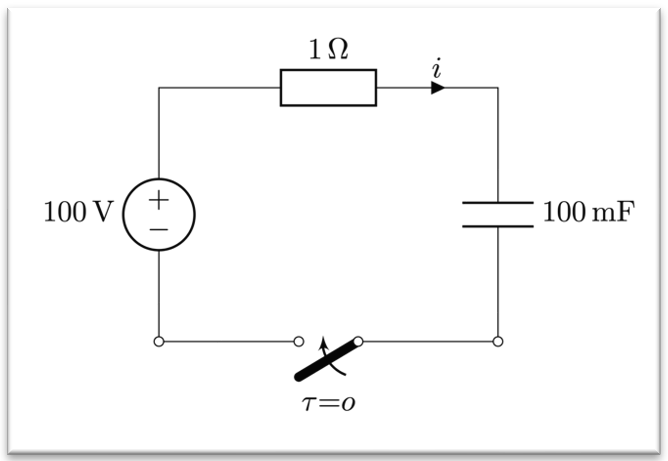
Charging a capacitor is actually more an exercise of forcing electrons apart from each other
Applying a DC voltage to a capacitor will cause current to flow immediately.
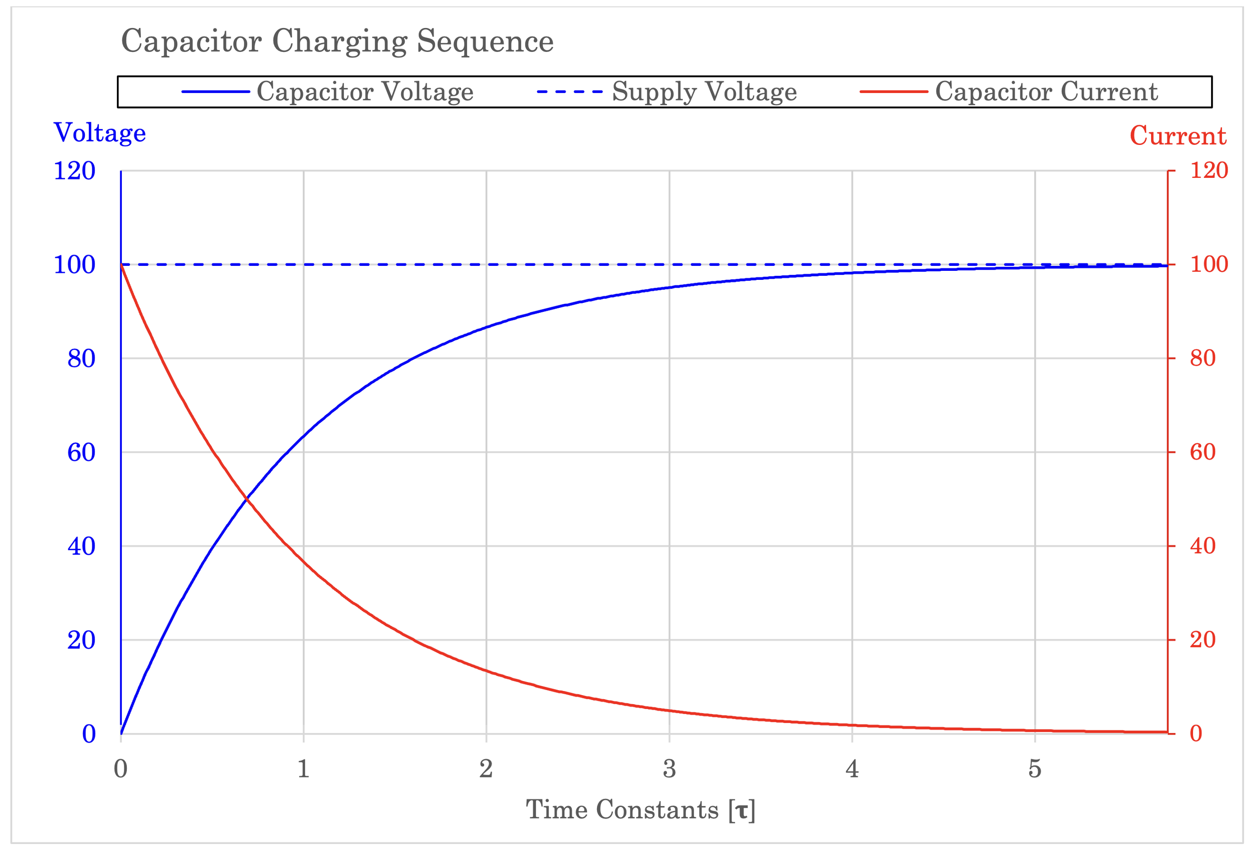
It will first flow rapidly into the capacitor and quickly reduce in an exponential fashion. Its voltage drop will increase from zero to eventually the same voltage as the voltage applied to it.
This X could almost be a grafitti signature
In the mechanical world, let’s start a motor, turning the shaft and starting to wind up the spring. First pay attention to the fact that the motor is an analogy to a voltage source, not a current source. This means that the motor outputs a given torque, not a given rotational speed. When the motor feels little load, it will spin very fast. When load increases, it slows down until its torque is insufficient to make the shaft rotate. Likewise, a voltage source outputs a very high current when there is almost no resistance (a short circuit), but when the resistance gets huge (open circuit), current goes toward zero.
So, back to our spring: The rotation will cause it to compress and tighten. Rapidly in the beginning when it is easy to tighten the spring. As the spring is being increasingly tightened, the torque will finally be insufficient to turn the shaft any longer and it will come to a standstill. Rotation has ceased; current has stopped. The spring is as charged as the motor can charge it. Further charging requires a stronger motor with more torque, but if the motor is too strong, the spring can break if wound up too much. Equally, charging a capacitor to a higher voltage than its rating can cause it to either say poof or bang and release a weird smell.
Anyways, the spring is now holding the same torque in its metal spiral as the motor can provide. This is potential energy. The shaft must turn for the energy to change. To charge more, a higher twisting force must be applied. To discharge, opposite rotation is needed. No rotation equals no change of energy.
Discharging the Capacitor
It is not usual to pull 100 amps in such diagrams
When a capacitor is charged, it behaves very much like a small battery with a voltage that decays as it gives up energy.
Connect it to something, and it provides current while steadily discharging. The voltage and current declines as its stored energy decreases in the same exponential way as when charging.
In the graph, a 1-ohm resistor was used to both charge and discharge the capacitor. Even though the current seems to spike during the first milliseconds of the charge and discharge phase (𝛕 = 0 and 5), it is simply that 100-volt supply divided by the 1-ohm resistor, hence 100 amperes.
The change in current after that initial point is due to the change in charge inside the capacitor; its voltage is defined as charge divided by capacitance (eq. 15), and as the capacitance is constant, changing the charge has a direct effect on the voltage.
It is also apparent that a rapid change in voltage makes the capacitor “invisible” to the circuit; it has almost no voltage drop, it exhibits almost no reactance, it doesn’t oppose current. Initially, the resistor is the only limiting factor of the current until the capacitor started to store charge and slow everything down.
Equation (13) shows this: capacitor current depends on how fast voltage changes. And every time the voltage changes, the capacitor reacts by adding or releasing charges from its plates. The faster the voltage is changing, the more current is moving to or from these plates. When voltage is not changing, the charges stay put. No current flows.
Exactly the same equations are valid for our spring. If we start with a fully relaxed and discharged spring, adding torque to it will in the beginning make the spring spin very fast. This is due to equation 14; a large change in torque causes a high angular velocity. And according to equation 16, as rotation starts to accumulate, more torque is required to uphold the same velocity. Hence equation 14 gets less change of torque and angular velocity decreases.
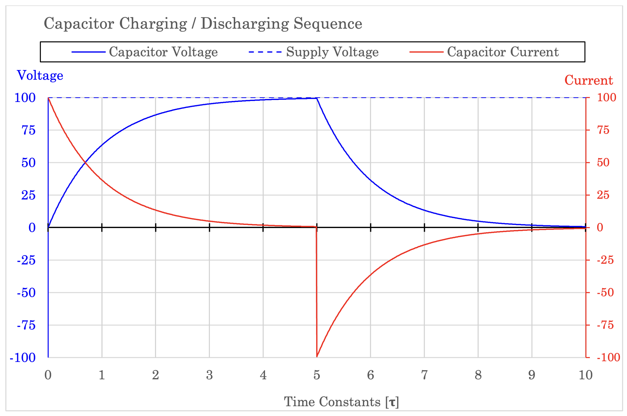
The red dip looks very violent compared to the rest of the red curve, but it is equally violent at t=0
But WHY?
Ok, so now we understand that inductance and capacitance create delays in how the current or voltage respond to change. The questions some might ask are; why are we using them in the power system at all? And what relevance does this have to reactive power?
The inductor’s slow response to current is actually quite useful in many different grid applications such as filtering, compensation and current limiting. But more often, inductance as phenomenon appears as an unavoidable, (although, valuable) property of electrical machines and transformers. Inductance and capacitance also appear in regular power cables and power lines (but no longer as a very valuable property).
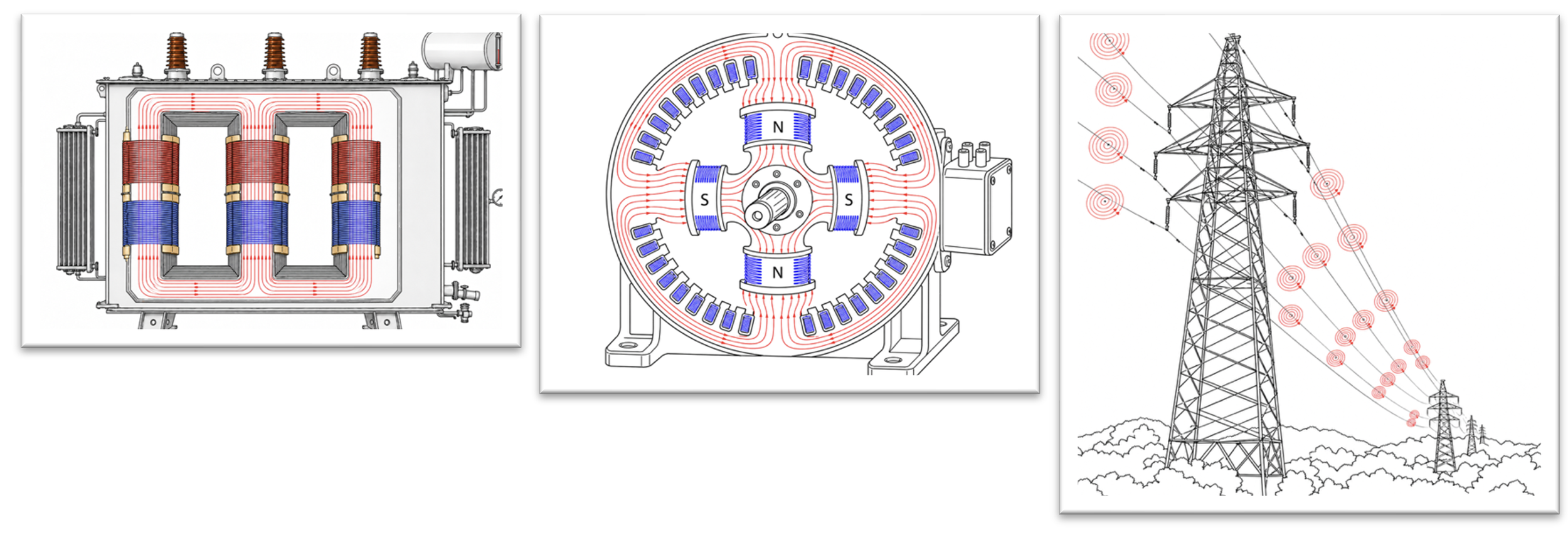
The usual suspects: transformer windings, motor windings and looong transmission lines
In transformers, inductance is needed to create the magnetic field required to transfer electrical power between windings which are isolated from each other. In motors and generators, the inductance creates a magnetic field to transfer mechanical power between the stator and the rotor. Both of these machines are widely used in power systems, and they are the main contributors to reactive power.
Large power lines, like the ones you can see stretching across the landscape from the airplane window, also exhibit surprising amounts of inductance. Long power cables, however, can start to exhibit capacitive behavior, and in some systems, this must be compensated by adding inductance.
Lastly, current by itself creates a magnetic field around the conductor, and the longer the transmission line, the more magnetic field energy is stored along its length. The line therefore accumulates significant inductance and starts to exhibit noticeable electrical inertia. The same would apply to a very long shaft; even if a short shaft is easy to turn, it would not be as easy if the shaft were ten miles long.
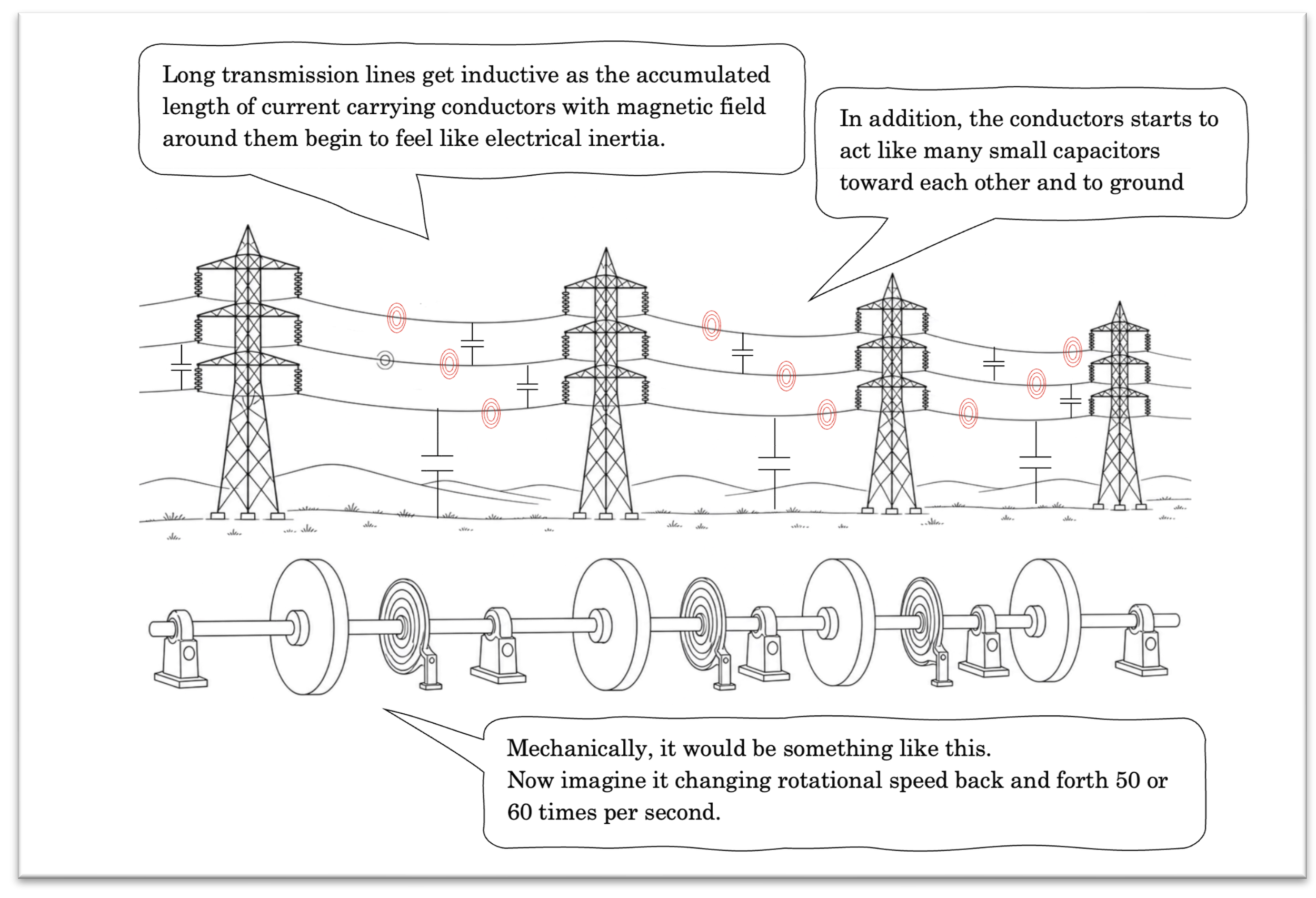
Imagine a mechanical power system across fields and planes
Reactive Power – Finally!
Until now, we have not really explained what reactive power actually is. We have barely touched upon it. Instead, we have droned on and on about inductances and capacitances, shown a lot of charts with red and blue lines heading in different directions, and schematics of components and switches. You may feel more confused now than you did fifteen minutes ago. You are also entitled to feel cheated of an explanation and argue that we have tons of loose ends here.
We will start tying them together now.
What we have learned until now is that inductive or capacitive effects make current or voltage react differently from one another in a way that shifts them out of sync.
Reactive power is most often defined for sinusoidal steady-state AC[1]. In that world, the voltage and current are always changing.
If the power system is inductive, it means that the magnetic field is in a continuous state of change, and because of that, the current is lagging the voltage. The opposite is true in a capacitive circuit; the current is leading the voltage.
But first (oh no, not again), we will look closer at how a power system looks when there is no reactive power at all:
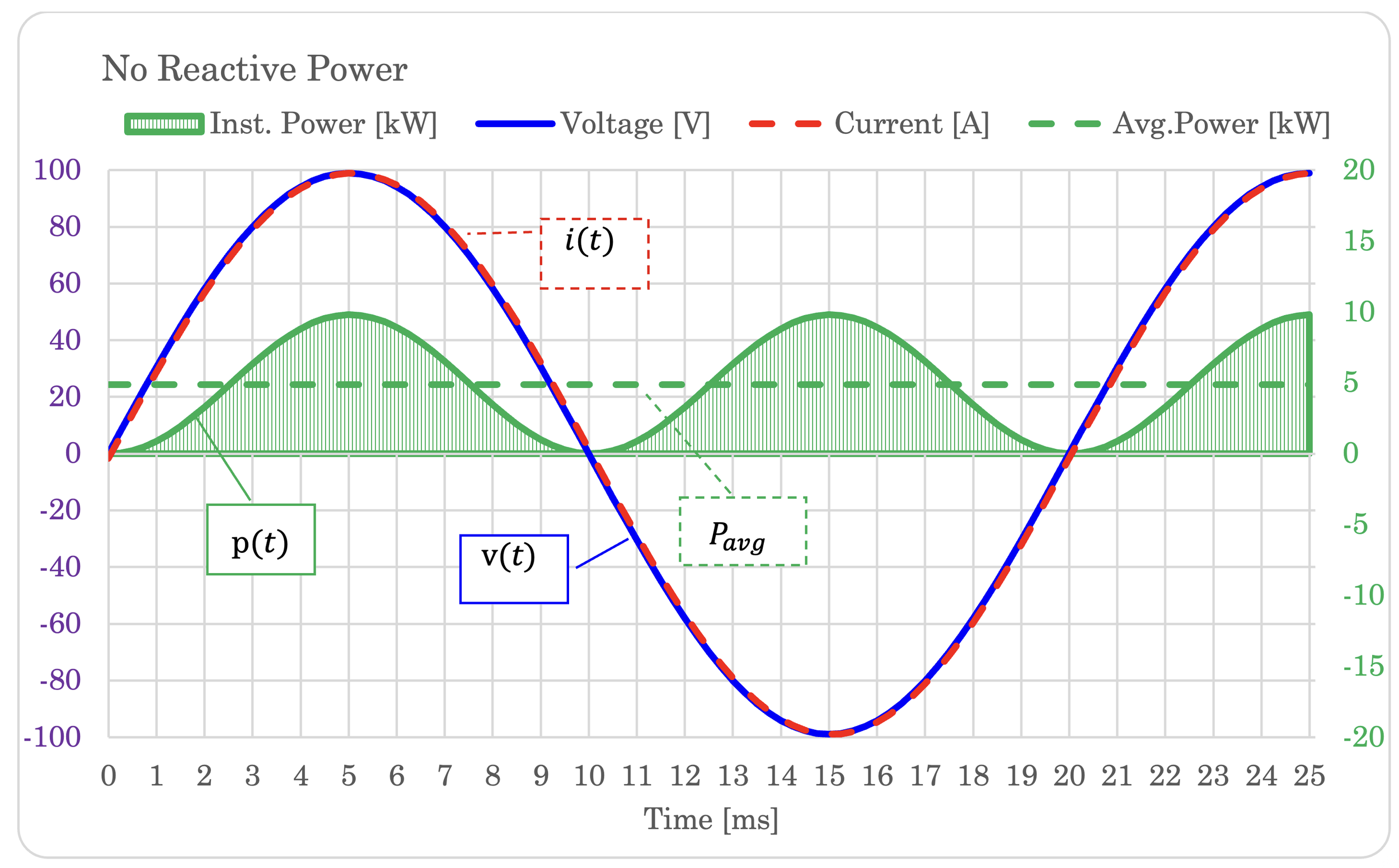
What you see in the graph is the blue voltage waveform, the red current waveform and two different green lines for power. The sine-wave-shaped on is the instantaneous power, which is the product of the two formers: . The dotted line is the averagepower P.
In the above figure, voltage and current are in phase. They are crossing the zero line together, every time. Notice that the whole p(t)-curve is above the zero point, meaning that power is positive all the time (well, not exactly at the zero-crossing).
We can call this a resistive circuit because it is neither inductive nor capacitive.
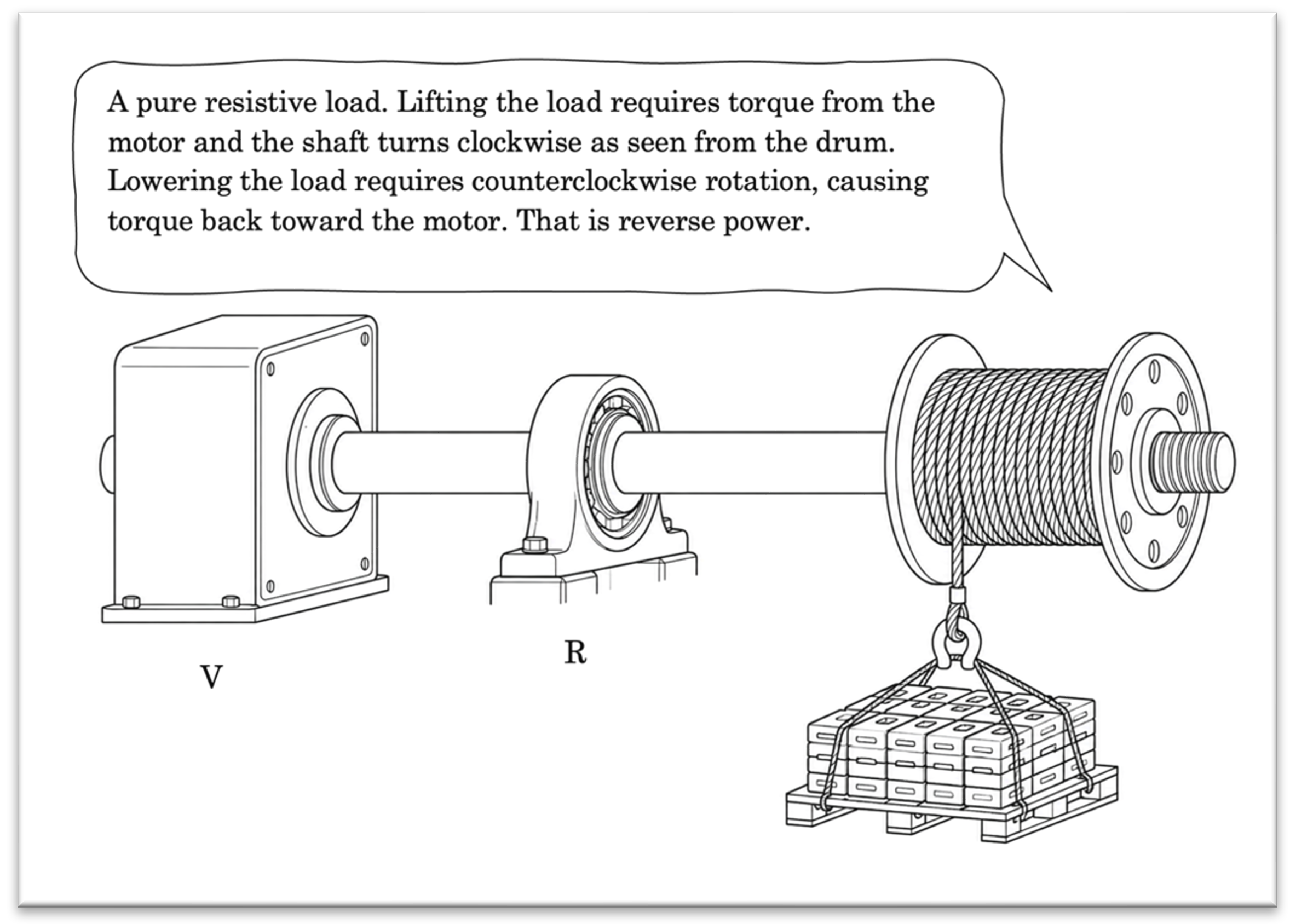
Some readers might point out that AC rotation on the shaft doesnt move the load much on average. Just imagine that the inside of that drum features some elaborate gears which makes it rotate in one direction either way. (And come on, at some point the analogy would reach its limit)
Now, let us connect a large inductive load to make the current lag the voltage:
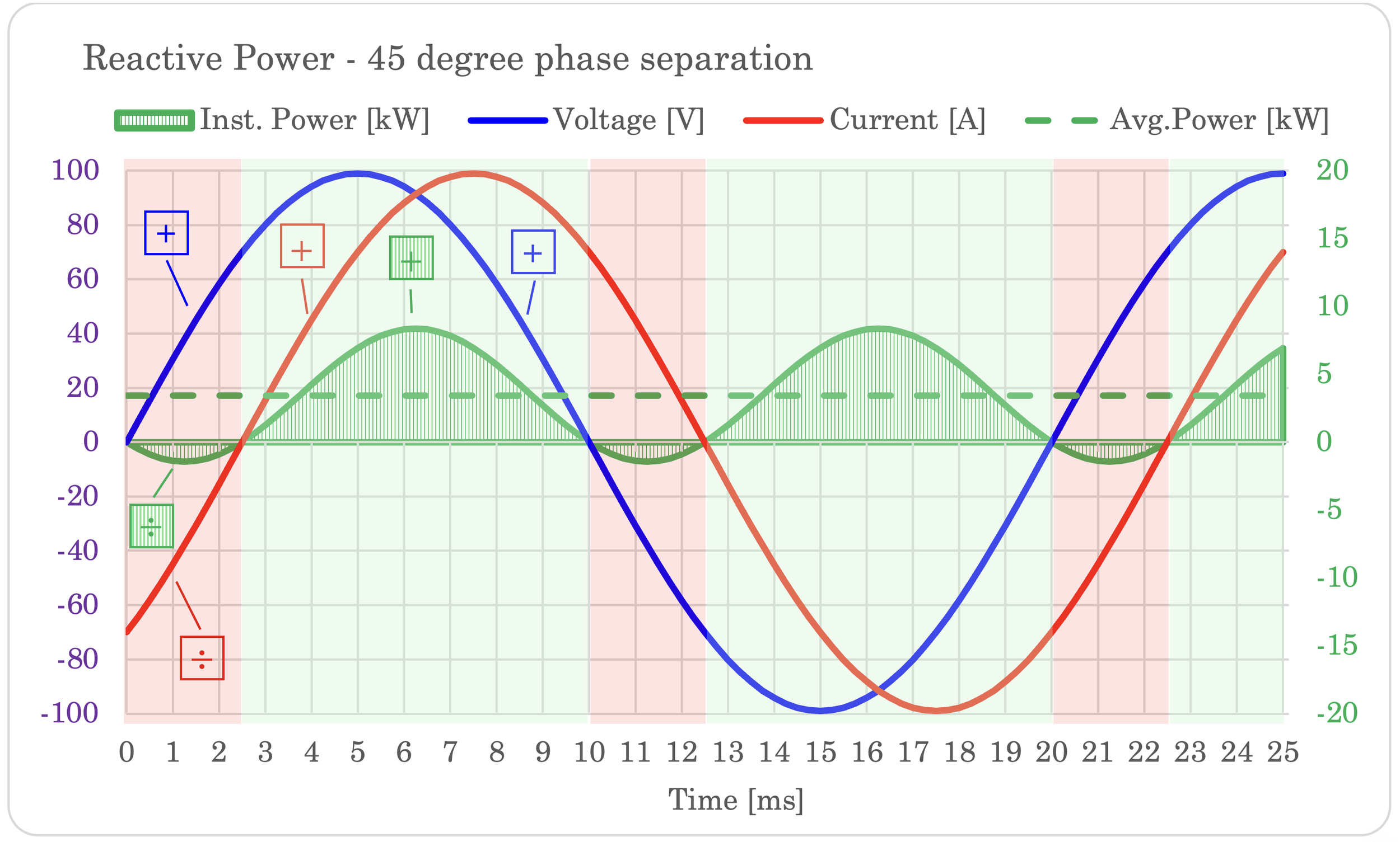
Compared to the first graph with resistive load, something new is happening:
At 0 ms, the voltage is crossing the zero and is starting to increase from zero toward 100 V. But the current is still flowing in the opposite direction. In the mechanical analogy, this corresponds to torque being applied in one direction, but currently the shaft is rotating in the opposite direction, albeit slowing down. The net flow of power, as the product of torque and angular velocity, is negative. This is forcing the supply to absorb power instead of delivering it. Electrically, as voltage is positive and current is negative, power is also negative, flowing backwards to the generator.
At 2.5 ms, current is finally slowed to a halt and starting to flow in the same direction as the voltage. Until slightly past 10 ms, they both agree on the direction and the product is positive. Power is flowing to the load.
Between 10 and 12.5 ms, the current is still positive, but the voltage is increasingly negative. This is the same scenario as the first one, but now the load is pushing torque back toward the supply in the opposite direction. Alas, the power is yet again flowing back to the generator.
Between 12.5 and 20 ms, both voltage and current agree on being negative, so the product is positive. Power is now flowing toward the load.
If this load were connected to a generator, it would feel short bursts of reverse power every 10 ms. The duration and amplitude is short enough that it would normally be absorbed by the inertia of the generator’s rotating mass, together with the flexibility of the couplings between the generator and its prime mover.
In the extreme case where the load was purely inductive, it would look like this:
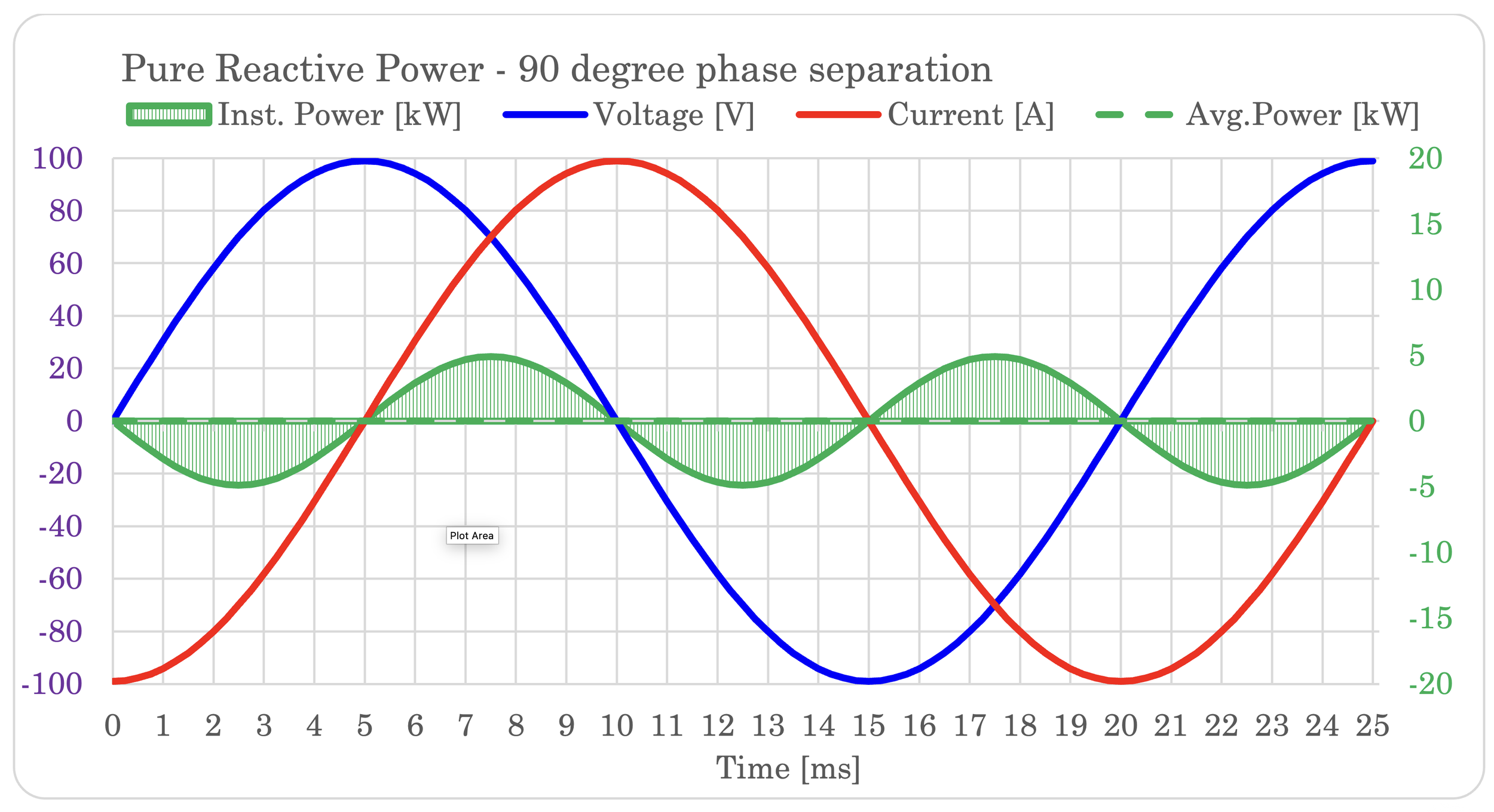
The current is here delayed by 90 degrees. Every 5 ms, the direction of power is changing direction in a manner that makes the average value zero.
In a capacitive system, the same would be true, except that the current would be the leading wave form. In the graph, red and blue would swap places.
We will now take a short intermission from reactive power: As we are splitting current from voltage in ever larger degrees of separation, we are now shifting into something that has nothing to do with reactive power. I want to mention it anyway as it follows naturally when we are playing around with these graphs and angles.
For phase shifts between -90 and -180 degrees, the average power is decreasing below zero until reaching full negative active power at 180-degree separation. This is called reverse power, and at 180 degrees, there is no reactive power involved.
You should also know that current and voltage do not “shift” sideways into the reverse power territory. It is more like current being flipped; imagine the amplitude of the current’s sinewave reducing until reaching zero and then starting to grow into the opposite side of the zero line. That is what is actually happening. If the current is already phase shifted due to reactive components, that will stay as is.
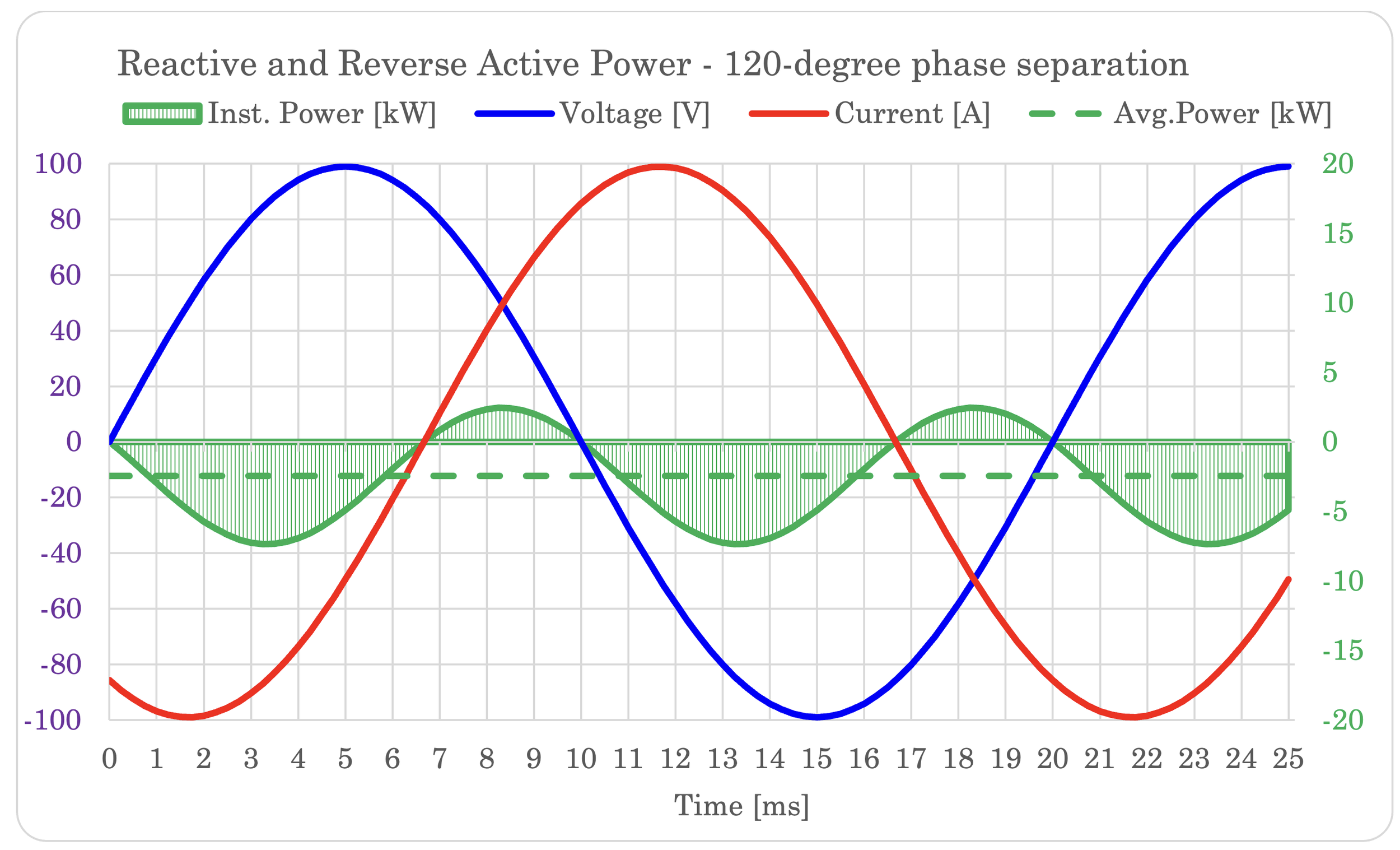
In the graph, showing phase shift of -120 degrees, you will notice that the average power P now is below the zero line. At the same time current and voltage do not cross the zero line at the same time, meaning we have both reactive power and reverse power.
Power is still moving back and forth between the load and the supply, but the total load in average is negative.
The next graph is showing reverse power with no reactive component:
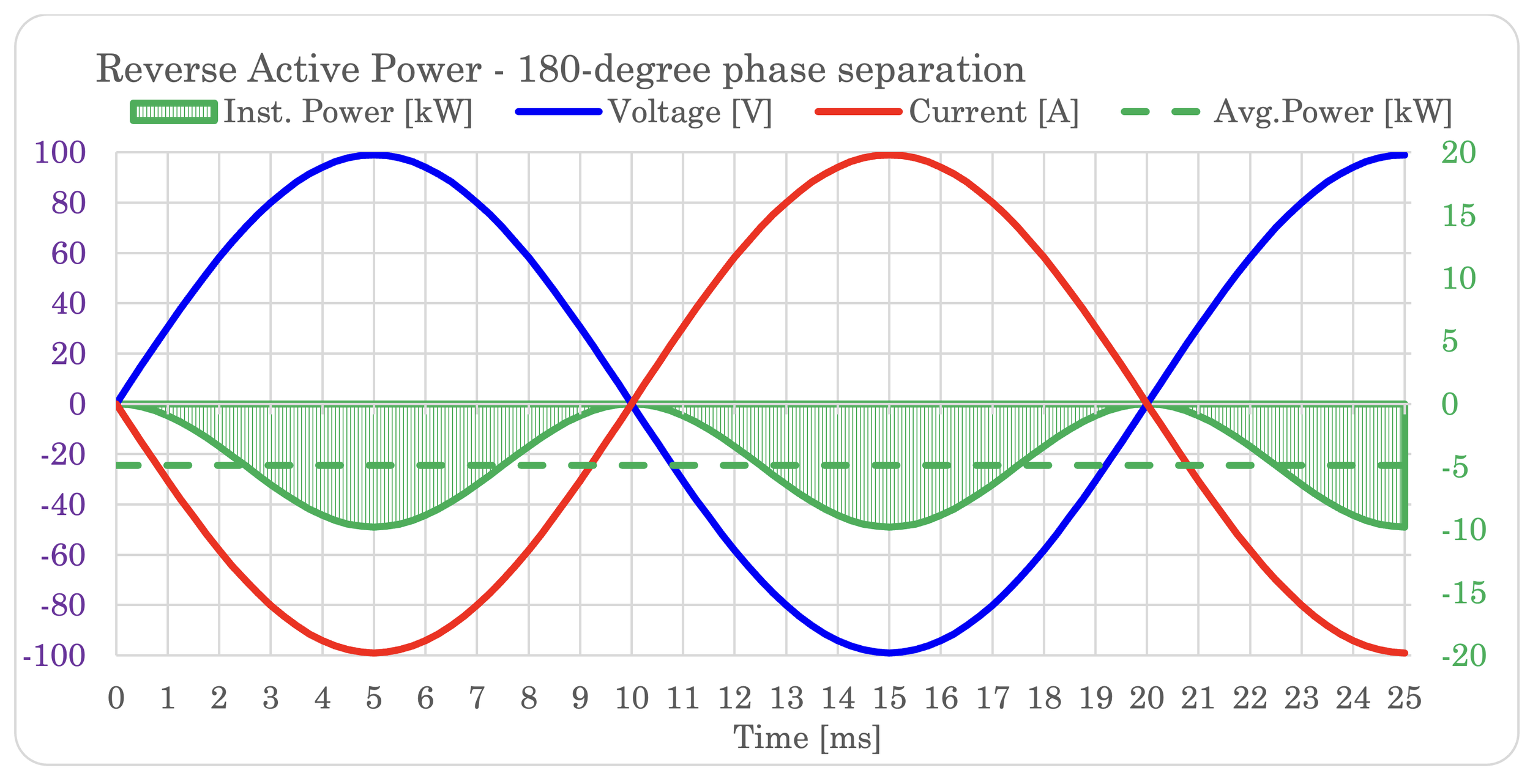
Notice that current and voltage are crossing the zero line at the exact same time again. The phase “shift” has taken a full 180 – literally.
This case is the mirror of the first case where the load was purely resistive. It still is purely resistive, but it’s not a “load” anymore. It is supplying power to the generator.
In our mechanical analogy, it means that our prime mover is trying to apply forward rotation as it attempts to lift the load. However, the shaft is subjected to a larger opposing effect, forcing it to rotate in the reverse direction. Every time the motor tries to push clockwise, the shaft rotates counterclockwise. This is perfectly synchronized, but opposite.
In the real world, reverse rotation is not a thing.
A generator shaft does not reverse direction when subjected to reverse power flow. The power flows backwards — from load toward generator — but the shaft keeps spinning in the same direction it always has. You would be forgiven for letting the analogy blur this, since we have spent considerable effort associating current to rotation. But here you must keep two mental models strictly separate: the analogy, and the actual machine.
Reversing the physical rotation of a generator in a power system is practically impossible during normal operation. It would require either switching the phase order of the system (not something one simply does) or commanding the prime mover itself to reverse direction, which most prime movers are mechanically incapable of. A steam turbine spins one way. It will continue to do so regardless of which direction power happens to be flowing. A water turbine is installed to rotate the way the water pushes it. An engine could in theory run in reverse — and operated in isolation, the directly connected generators and motors would dutifully follow, spinning the wrong way.
Connecting a reversing engine to a grid, however, would be a futile attempt to make every other generator in the grid run backwards. It would be immediately outnumbered and disconnected by its protection relays.
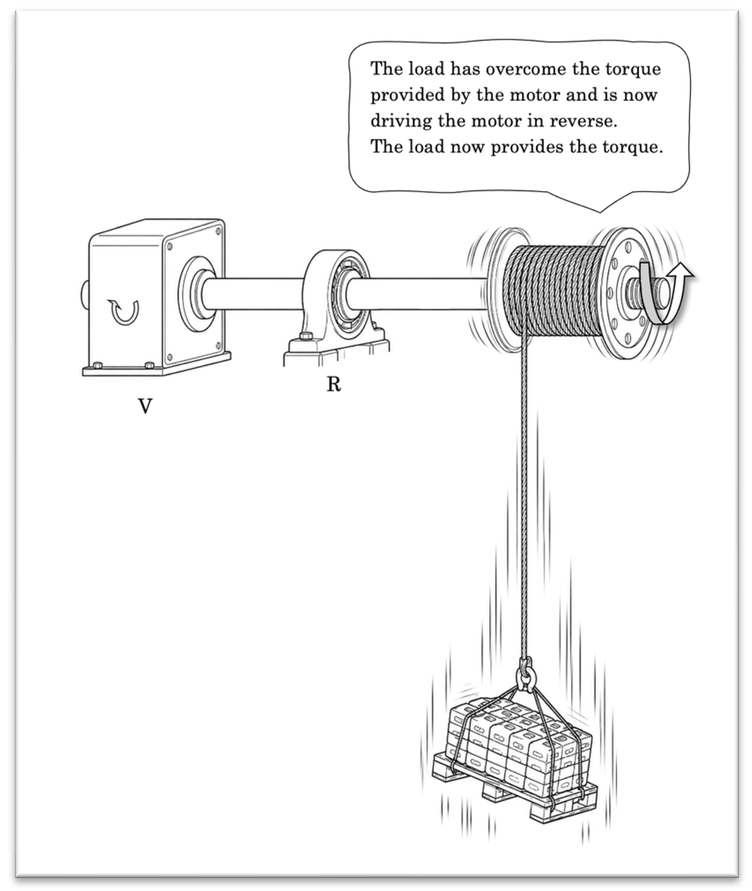
This is also why one never walks under suspended loads. Never.
[1] Reactive power does however also exist outside pure sine waves, but I was not planning on going to full depth on harmonics, unbalance and non-sinusoidal waveforms in this article. Sorry. Not sorry.
So, what is reactive power?
In one sentence, I would say something like this:
“Reactive power is the collective and accumulated stubbornness of components hating to change, being forced to continuously change.”
The voltage in AC power systems are changing endlessly. To the inductor and capacitor’s dismay, there is no such thing as steady state. The ever-changing voltage is forcing the them to first absorb energy, then return the same energy, over and over again. This change of direction occurs every 5 ms in 50 Hz power grids (or around 4 ms in 60 Hz grids).
In our mechanical world, imagine yourself working the handle of a shaft with a flywheel. Your job is to speed it up in clockwise direction, but when getting to a certain speed, you must slow it down and start rotating it in the counterclockwise direction. While trying to slow it down, the handle is now forcing your hands around as the energy in the flywheel comes back to you.
That same energy you just spent accelerating the flywheel is being returned.
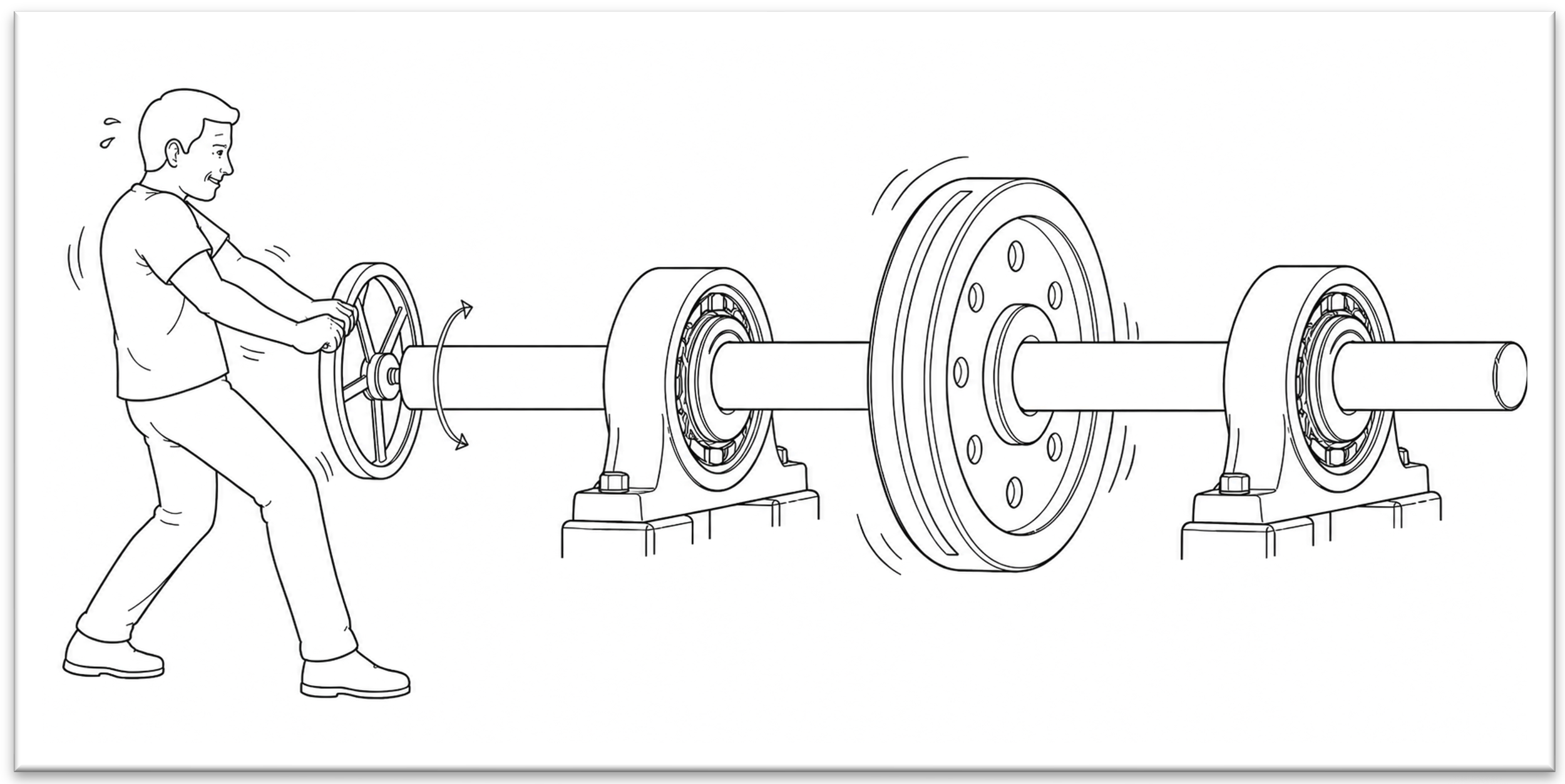
This exercise should be in gyms
If a motor was driving the shaft like this, it would feel high output power half the time, and equal reverse power the other half. It would always be net zero on average, but it would still need to be able to deliver the output power half the time. This sets firm requirements to the torque provider in the same way power plants need to be able to supply the voltage and current necessary to maintain these ever-chasing magnetic or electric fields.
The power associated with this back-and-forth field energy is what we call reactive power. We have designed an alternating power system consisting of very many, but very useful, magnetic fields. Now we must also deal with the consequences of those fields’ inertia and the effort necessary to change their direction 50 (or 60) times per second. Some might ask about the electric fields from the capacitors, but most reactive power in power systems originates from magnetic fields in inductive components. The capacitive part come from compounded parasitic capacitance between phases in power lines and power cables, and sometimes large-scale filters and capacitor banks are installed in power systems.
Being able to keep up with this back-and-forth energy has an electrical consequence as well: Even though the reactive part of the current does no useful net work over a cycle, it still creates real I²R losses simply by flowing.
The generator, transformers and cables cannot be sized only for average active power. They must handle the actual real-time voltage and current. Reactive current therefore occupies actual equipment capacity, creates real I²R losses, and contributes to voltage drop which must be compensated. This applies even though the associated energy is returned over the cycle, and this is why transformer capacity is measured in volt-amperes such as kVA and MVA instead of kW and MW: The equipment must withstand the total voltage-current burden, not just the part that becomes active power.
Ergo, active power is the net energy transferred over time. Reactive power is the swinging energy exchange required by magnetic or electric fields. Apparent power is the total voltage-current burden the equipment must be sized for.
OK, so reactive power is a stubborn beast. What can we do about it?
Mitigating reactive power
Reactive power in a power system is generally not desired because it is expensive to transfer, expensive to produce, creates real losses and requires over-sized grid equipment.
So how do we reduce our reactive power in the grid?
There are generally two ways. In modern electrical devices with power electronics in them, it has been common to add special circuitry which cancels most of the device’s consumption of reactive power. So seen from the grid, the device’s current and voltage are more or less in phase, although internal reactive exchanges may still exist. This is called power factor correction (PFC), and we will just leave it at that[1].
The other way is to make the reactive components shuffle the reactive load between themselves. This is a very nifty way of fixing a silly problem. It is not possible to decline inductance or capacitances their reactive power needs, but itispossible to create a much closer source. This will avoid the need of upsizing the grid and transporting the reactive power from far away.
Imagine you own a factory with a lot of electric motors which draw a lot of reactive power. Your factory’s ratio of active power to reactive power is so poor that the utility or grid operator kindly asks you to supply your own reactive power locally. The power plant is not willing to produce it from far away and transport it all the way over to you. It occupies power line capacity which otherwise could be used by active, billable, power, and it creates losses which their generators have to cover.
As most consumed reactive power is inductive, the solution is actually to add local capacitive reactive power. That is very fascinating.
In our analogy, if your factory has too many heavy flywheels on its shaft, the solution is to add springs (!).
Mathematically it is quite straightforward: inductance makes the current lag voltage, adding capacitance shifts the current back toward the voltage until they eventually are in phase. But that is only how it looks from the outside.
Inside, between the two components, reactive power is still flowing back and forth. But now, the capacitor supplies the reactive power. It is no longer necessary to send it from miles away.
When the flywheel has forward speed and is being forced to slow down, the spring is there – ready to uncoil. If we size the spring to match the flywheels’ inertia, they become a closed loop. As the AC cycle starts to reverse, the heavy flywheel inertia is forcing the spring to compress. Milliseconds later, the spring forcefully unwinds and pushes the flywheel back the other way.
The spring and the flywheel are now exchanging the same energy back and forth. From kinetic to potential to kinetic again. This is only seen between the two components; it is not visible from the outside. The upstream grid no longer has to carry the back-and-forth energy needed to brake and accelerate the flywheels – it only has to provide the active power to overcome friction and serve actual billable load.
My top wish list for christmas: a real mechanical model of this
[1] I wanted this to be a power engineering article, not a power electronics article. The former is simple and beautiful; the latter is difficult and sleep depriving.
Lastly, how does reactive power feel like?
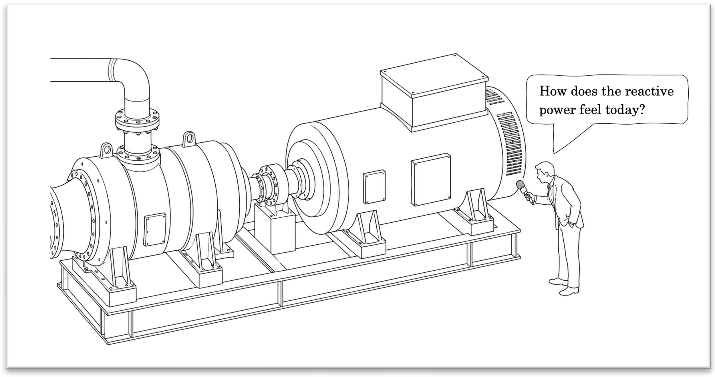
The generator declines to comment
If you are a generator, or pretend to be, how would it feel to deliver reactive power? Let’s focus on generators with rotating mass first, and not the “synthetic” generators consisting of power electronics from windfarms and solar arrays. Those don’t even have feelings.
The rotating generator and its prime mover, like a steam or water turbine or a gas engine, carries massive amounts of inertia. They are heavy and they rotate fast. There are also flexible couplings between the generator and the prime mover, dampening vibrations and small ripple in the torque.
As we have seen, reactive power is short-term active power which is being delivered and returned approximately every 5 ms. This causes ripple in the torque as seen from the prime mover, but the huge amount of inertia from the shaft and generator rotor absorbs most of it like a boss with no complaining.
But what if we have a pure inductive load? Does it mean that all the load is coming and going every cycle? How would that be? Would the prime mover be forced to rotate backwards for 5 ms, before it could rotate forwards for the next 5 ms, and then again rotate backwards?
No. Because reverse power is not the same as reverse rotation. Bookmark that in your head.
What the prime mover actually notices is that the load briefly disappears, and that something is momentarily helping it turn. The prime mover only cares about one thing: maintaining its speed setpoint, which translates directly to grid frequency. When load increases, the governor notices the speed dropping and opens the throttle (more steam, water or fuel) to compensate. When load decreases, or briefly reverses, the prime mover suddenly gets help turning and the governor can relax.
When reverse power becomes sustained and significant, the prime mover is effectively being driven by the grid rather than driving it. Some prime movers handle this gracefully. Others find it quite dangerous — a steam turbine without steam flow through its blades, for instance, is not a happy machine.
But in the reactive power timeframe of 5 ms pulses, it never comes to that. The inertia and coupling flexibility absorb the ripple entirely, and the prime mover goes about its day largely unbothered.
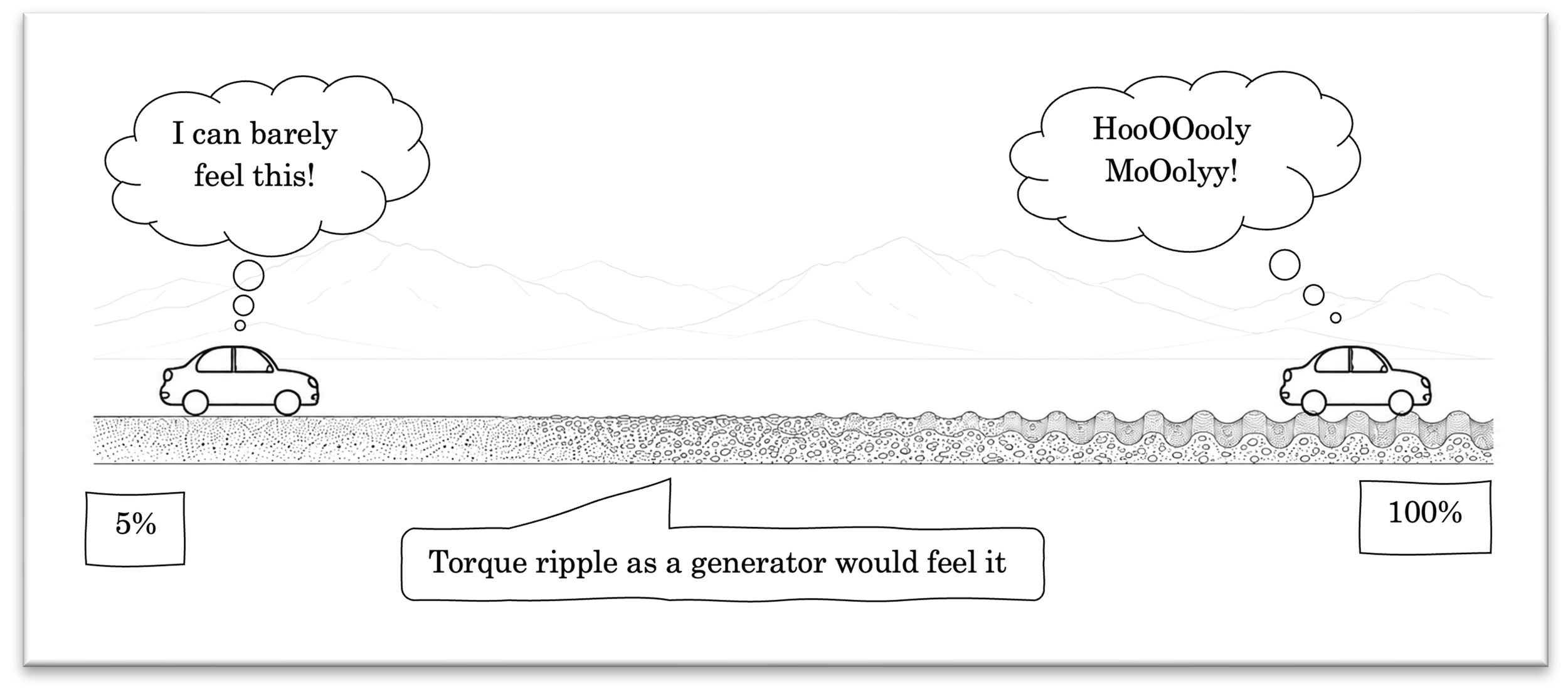
I can describe this using a, for many, familiar analogy – and I reckon you like analogies if you have read this far. Driving a car. Driving straight and then going up a hill, you have to press more on the accelerator pedal to maintain your speed. At the top, you can relax a little, and going downhill, you can take your foot off completely if the hill is steep enough. The wheels are now forcing the drivetrain instead of the other way around. That is reverse power; gravity is pulling your car downhill. Reactive power in this analogy would be small bumps in the road, like driving on cobble stone. Most of the car’s suspension and forward motion will absorb it, you don’t have to micromanage your accelerator pedal to maintain your speed.
The more reactive power you are forced to deliver, the deeper those cobblestones get. At 100% reactive load, it’s like driving over a washboard dirt road; your car maintains its speed, and you don't need to press the gas, but the mechanical stress on your suspension is violent.
This is also what usually happens if a driver is following the GPS too closely in Norwegian rural areas
And now, after all of that, I am going to pull a small rabbit from the hat:
Most of the sloshing we have looked at so far is easiest to see in a single-phase system. Real power systems, however, are usually three-phase.
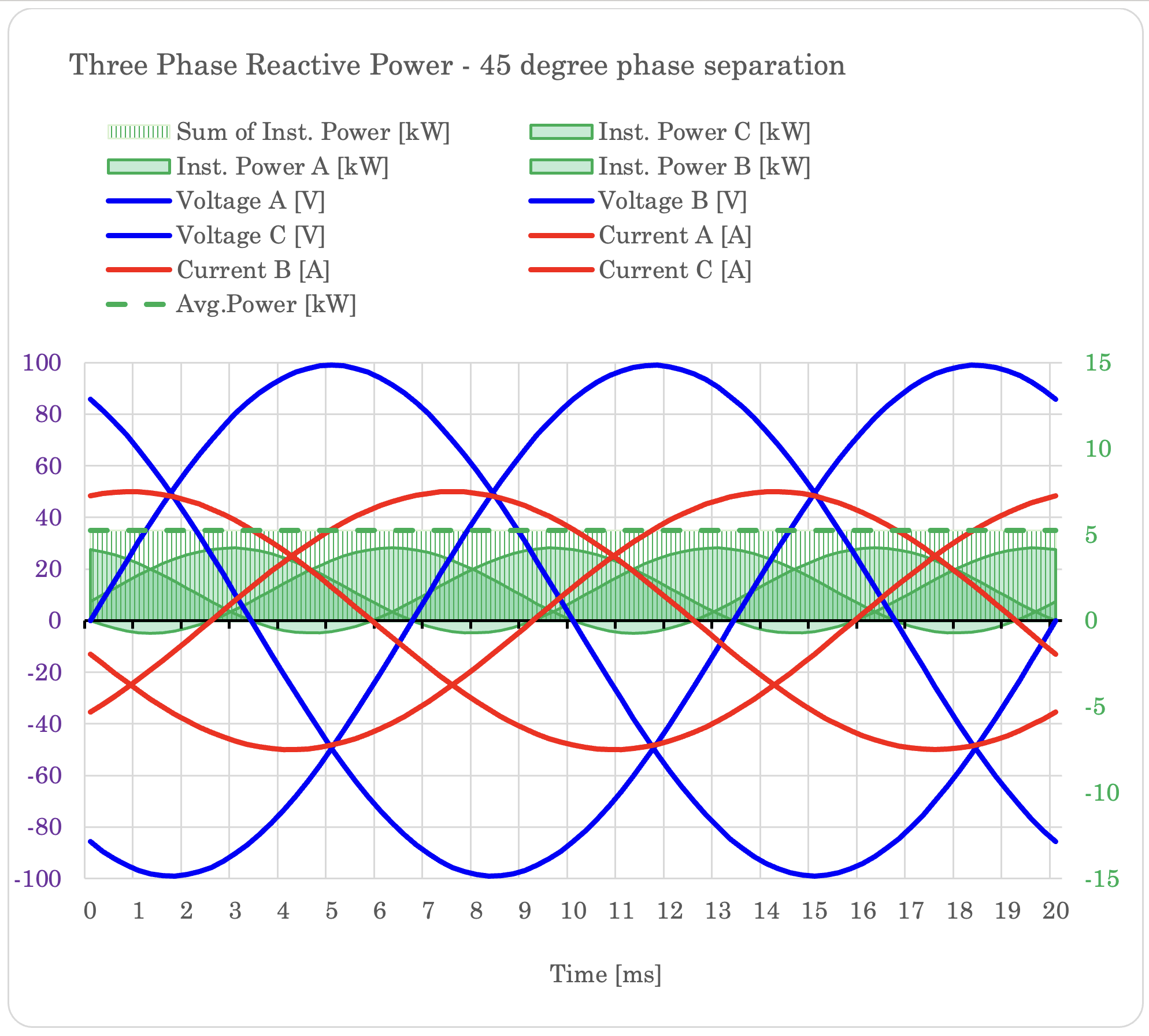
In a three-phase generator, the stator windings are physically placed 120 electrical degrees apart. The voltage and current waveforms are also 120 degrees apart. This has a remarkable effect: when we add the instantaneous powers from phase A, B and C, the pulsations cancel!
This does not mean that reactive power has vanished. Each phase still exchanges energy back and forth with the magnetic field and the connected network. The windings still carry reactive current, and that current still causes losses, voltage drop and equipment loading.
But the rotor does not feel each phase separately. It feels the combined electromagnetic effect of all three phases. As one phase is giving energy back, the others are receiving it. The result is that the total electromagnetic torque becomes effectively stable in a balanced three-phase system.
So, the sloshing still exists in each phase separately, but it does not appear as a large back-and-forth pulsation on the generator shaft.
Just check out the graph: the instantaneous power of each individual phase still pulsates, but their sum is completely flat. The sum of instantaneous power from phase A, B and C is equal to the average three-phase power.
Just like that, huh?
Afterword
We have now fully translated fundamental electrical components into a mechanical sibling to better understand the phenomenon of reactive power. We understand why it behaves the way it does, what we do to prevent it and that it is very much not beer foam.
The useful aspect of the analogy we have built, is that you don’t need to remember the graphs or the equations, you can visualize the concept in a way that makes sense instead. If you are like me, you might even envision power lines, transformers and windings surrounded by slow and heavy magnetic fields, and appreciate why they require additional effort to keep changing direction fifty times per second.
And if someone is asking you about reactive power, you are much better equipped to explain it. You are also fully authorized to interrupt anyone preaching the beer foam explanation and suggest that you should take the wheel from here.
Good luck out there, and may the torque be with you.
The figures that almost made it into the article
The work in this article started back in 2018. The whole analogy, equations and mental model was created back then. But i had NO way of actually illustrating it. Simply couldnt do it.
Until now. It took weeks of prompting, inflicted serious mental wounds attempting to get an image model to draw the field lines correctly, getting it to make the cogs hit the right place and so on. I think it is fair to say that for each more or less successful image, there was about 40-50 throw aways.
But in the end, it was worth it. It made me able to share my own mental models with others who might learn something from it.
Cheers.
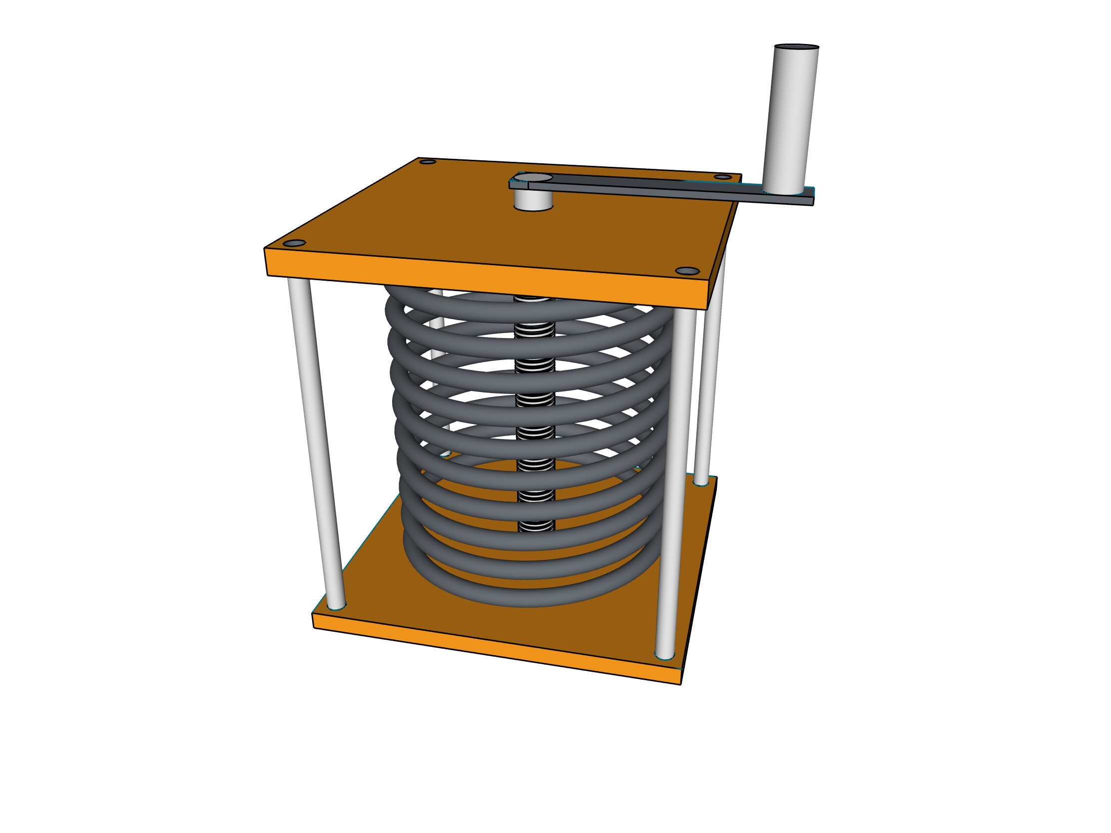
The very first model. Made with CAD software. It took way too long.
This is actually how i see power transformers
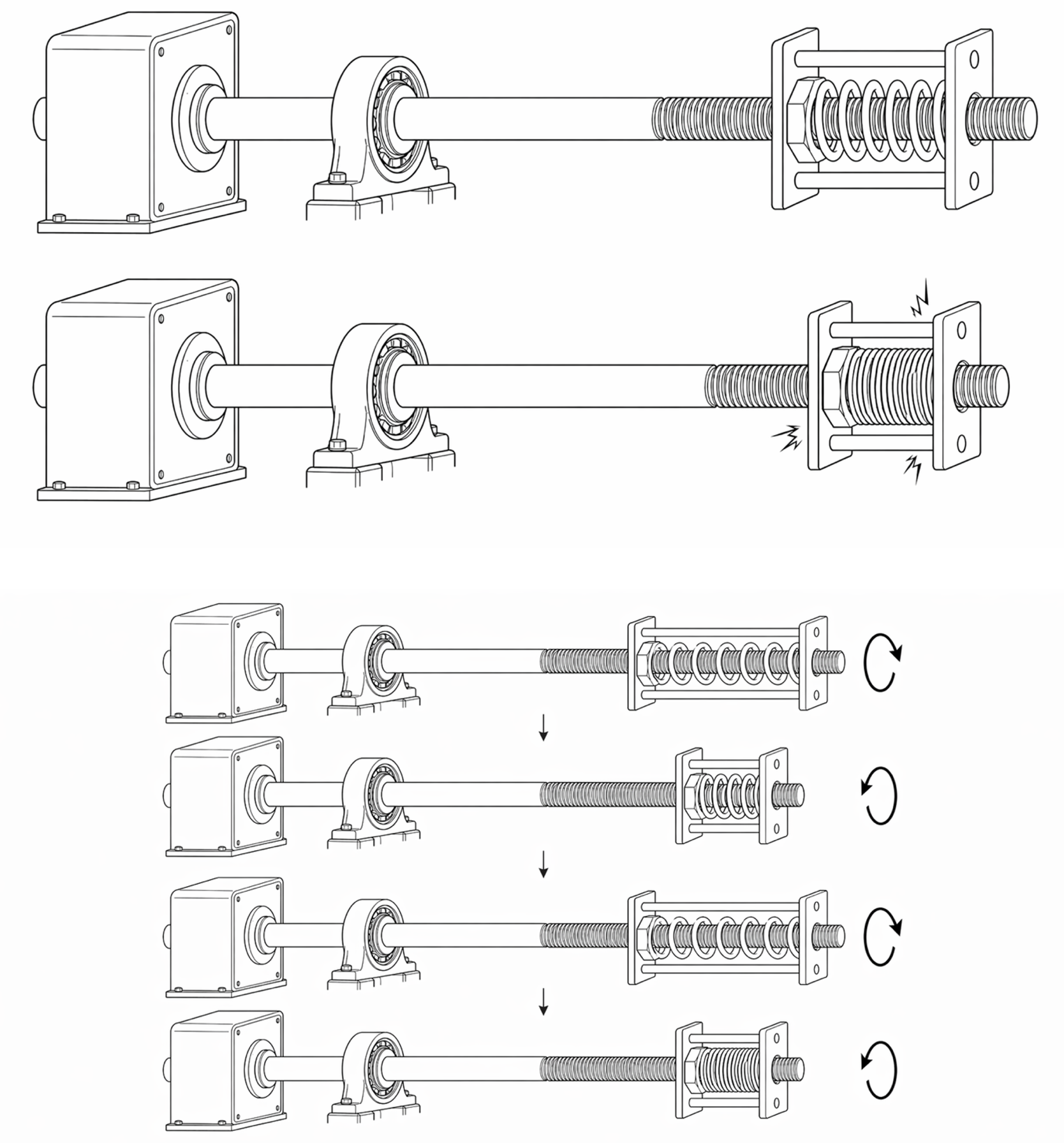
The first editions used a helical spring being forced to linear movement by a threaded rod. It works, but eventually I figured that the flat spiral spring was easier to explain.
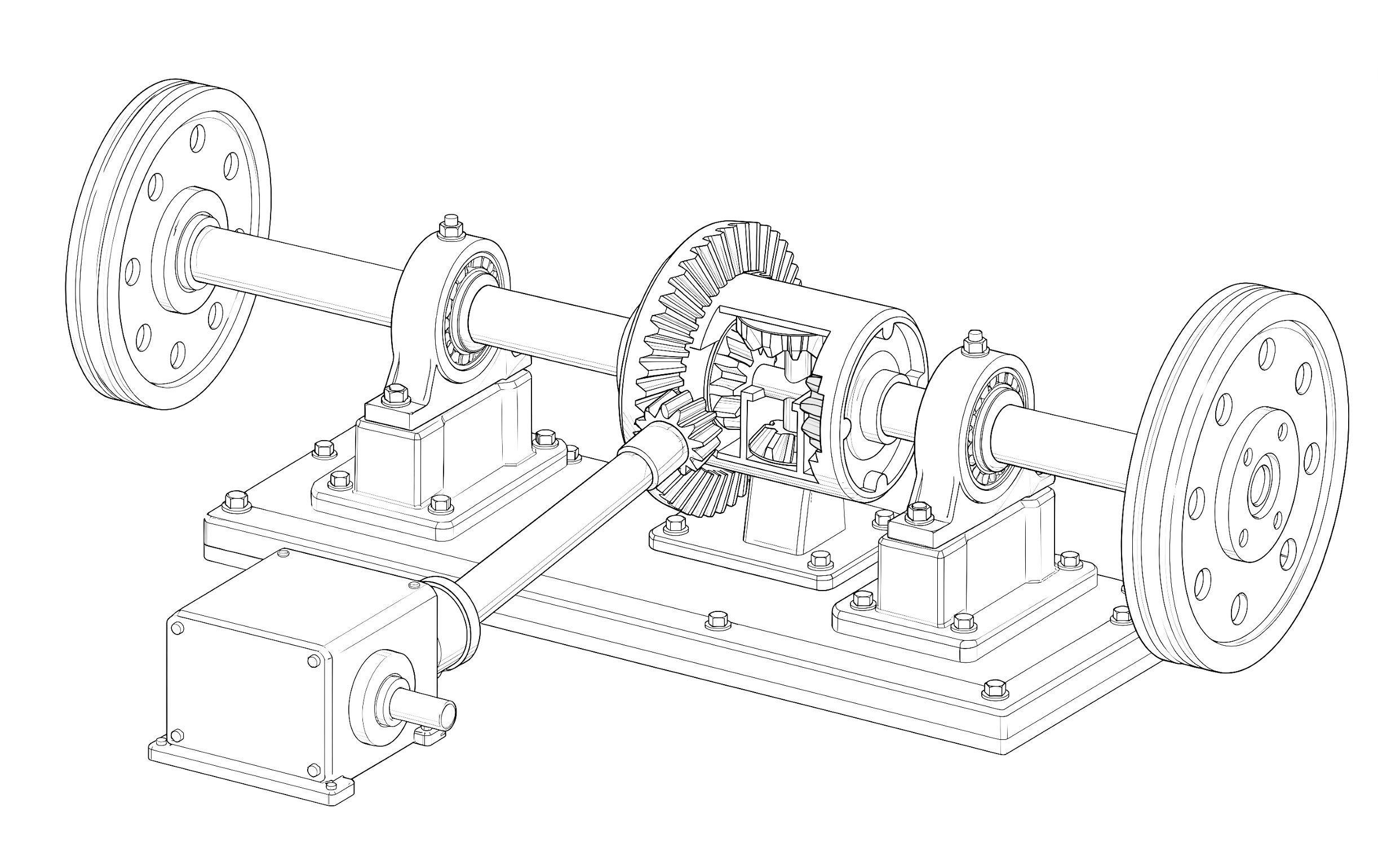
The differential mechanical equivalent to a paralell connection. It took forever to get it right.
I dont even remember what i was going to use this for